4140PWRR3

The NGTC-4140PWRR3 is a Dante™ enabled network power amplifier for the nexgentec™ audio distribution solution

Key Features

  • 4 x 140 Watt @ 4 Ohm – 1 x 200 Watt @ 4 Ohm bridged
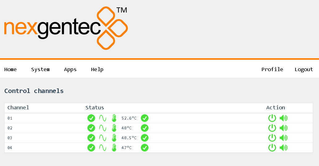
  • LAN control protocol
  • only 1RU high
  • Dante™ audio interface
  • Stereo digital power amplifier
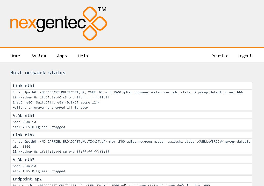
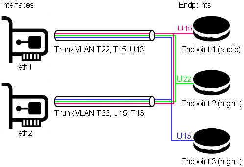
  • Manageable integrated 2 port switch
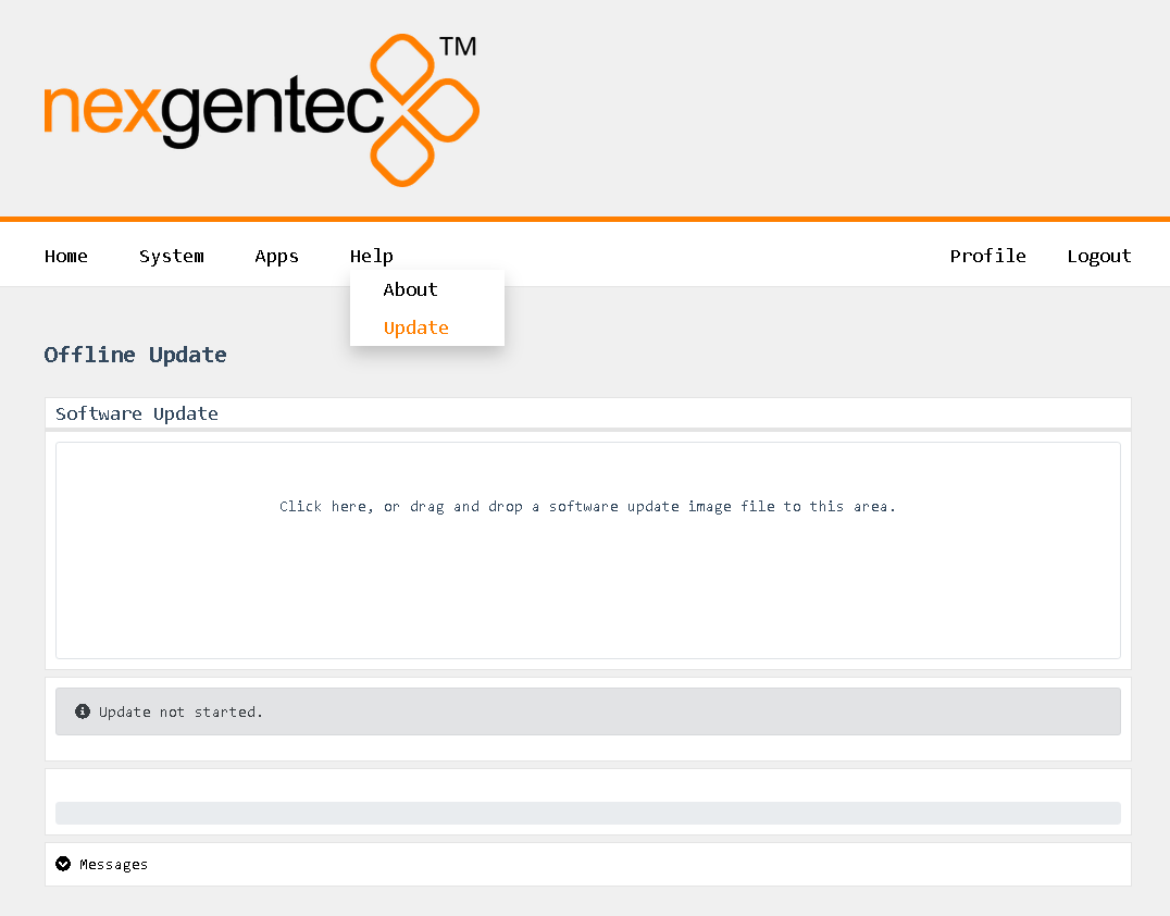
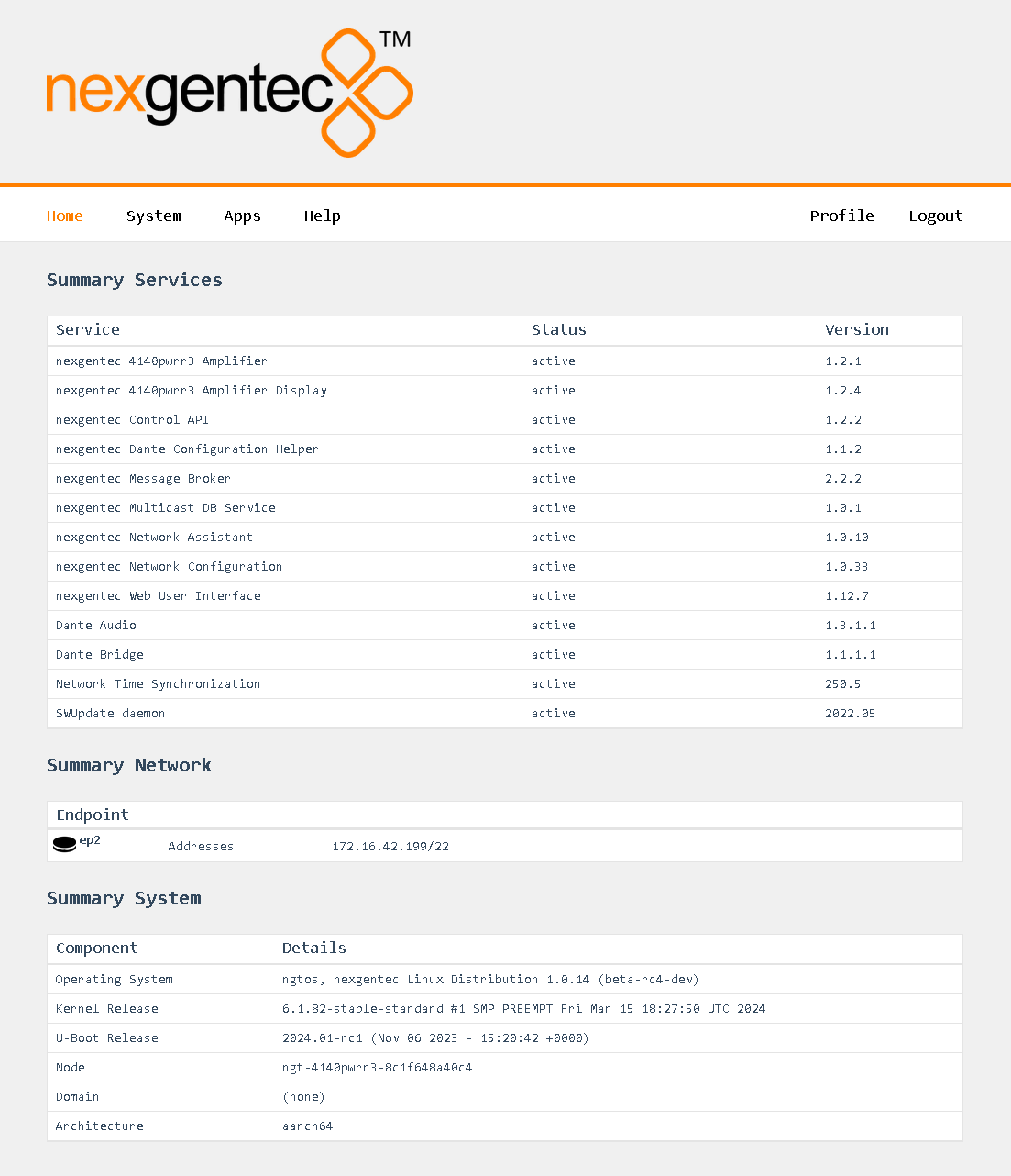
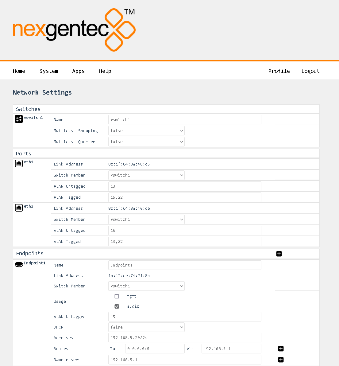
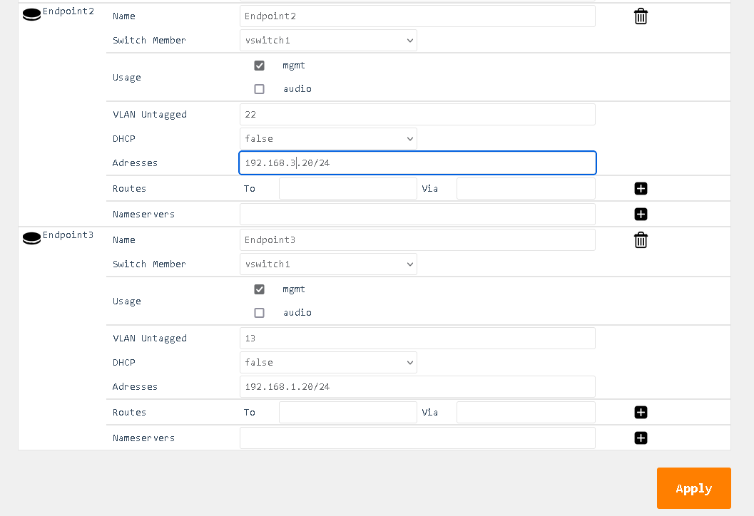
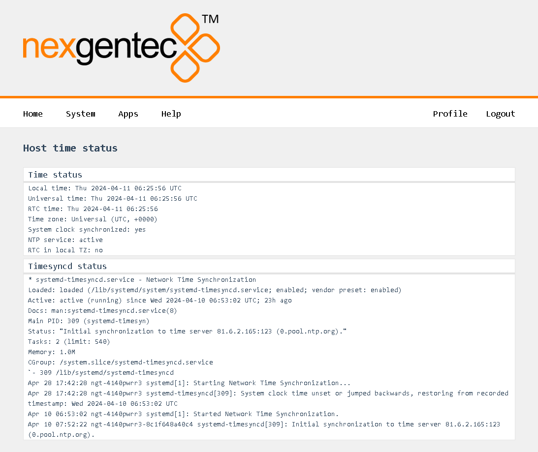
  • nexgentec ngtOS, operating system for control api, configuration and monitoring

Subsections of 4140PWRR3

ngtOS

Caution

Never downgrade to an older ngtOS, as it will result in a factory return of the unit in every case.

Notice

If you have multiple units to update, try the update on one and if it’s working as expected, proceed with all others.

Update Path

  • All units must be updated to 1.0.14 (beta-rc4) before upgrading to any higher version of ngtOS.
  • Future update paths will be published when available.

Update Notes

Version 1.0.14 (beta-rc4)

  • Beginning with version 1.0.13, a new method to configure the network of the unit was introduced. Existing configurations will be converted as accurately as possible. If the update fails, a default configuration is applied which sets eth1 to DHCP. Therefore, having a DHCP server present in the network is mandatory.

Update from 1.0.13 or lower to 1.0.14 (beta-rc4)

Caution

You may need help when updating units with ngtOS below version 1.0.13. Ensure that you are inside the office opening hours of Genesis Technologies Switzerland. (8am till 4pm CET +1)

Devices delivered before December 2023

Your unit(s) probably need some special treatment before the update. Please contact Genesis Technologies Switzerland at info@genesis-technologies.ch before you attempt to update.

Plan the Update

  1. Ensure that the unit you plan to update is connected to a network with unfiltered internet access. This is necessary in case service personnel need to access the unit using the built-in support tool.
  2. Make sure that you are within the office hours of Genesis Technologies Switzerland (8am to 4pm CET +1).
  3. Ensure that no one else is working on the network during the time of the update.

Run the Update

  1. Open a browser and enter the IP address of the unit into the address bar.
  2. Log into the web interface using the username ‘admin’ and the chosen password (default is ’nexgentec’).
  3. In the top menu bar, select ‘Help’ > ‘Update’.
    Picture Picture
  4. Follow the instructions shown.
  5. Wait for the unit to reboot

Change Log

Version 1.0.13 (beta-rc3)

  • Updated DEP to support AES67
  • Enabled display
  • Network ports can now be configured as a manageable switch, including IGMP settings
  • Enabled cluster support
  • Various improvements and bug fixes across all running services

Version 1.0.14 (beta-rc4)

  • WebUI: Returns to login after timeout
  • Network: Endpoints maintain the same MAC address
  • Display: Some graphical artifacts have been fixed

Known Issues

Version 1.0.5

  • The display is not working, it only shows the NGT logo

Version 1.0.14 (beta-rc4)

  • WebUI: Clustering configuration is missing
  • WebUI: Mandatory password change feature is missing
  • SNMP: Missing

Upcoming Features

Features Awaiting Implementation:

  • User configuration support for clustering
  • SNMP support

Apps

Configure Installed Apps of the Unit

Each installed app can be configured to a certain level via the web interface.

Info

The default login for the web interface is: Username: admin Password: nexgentec

Open a browser and enter the device’s network address in the address bar, then press Enter.

Picture Picture

Use the top menu bar to navigate to Apps and select the app to be configured.

Subsections of Apps

Amplifier

Using the top menu bar, navigate to Apps > Amplifier.

Files

Files > Log

Selecting “Files” will open the file browser where you can download and view the log files from the app.

Options

Options > General

logLevel

  • Select the log level for the app.

transport

  • Read-only: This field shows the internally used transport address.

Control

Control > Channels

Picture Picture

Status

  • These icons show the status of the amplifier channel. Also, the temperature is displayed.

Action

  • Use these buttons to turn the amplifier channel on and off. The amplifier channels can also be muted and unmuted. Be aware that due to a hardware limitation, channels 1 and 2 always follow the same power and mute settings, as do channels 3 and 4.

API

Using the top menu bar, navigate to Apps > API.

Files

Files > Log

Selecting “Files” will open the file browser where you can download and view the log files from the app.

Options

Options > General

logLevel

  • Select the log level for the app.

transport

  • Read-only: This field shows the internally used transport address.

api

  • Use the dropdown menus to select the Endpoint and the port to use for each protocol that the API can communicate with.

Broker

Using the top menu bar, navigate to Apps > Broker.

Files

Files > Log

Selecting “Files” will open the file browser where you can download and view the log files from the app.

Options

Options > General

logLevel

  • Select the log level for the app.

transport

  • Read-only: This field shows the internally used transport address.

Dante

Using the top menu bar, navigate to Apps > Broker.

Files

Files > Log

Selecting “Files” will open the file browser where you can download and view the log files from the app.

Options

Options > General

network

  • Select the interface to be used for Dante audio. This interface will be used for audio data transmission.

Display

Using the top menu bar, navigate to Apps > Display.

Files

Files > Log

Selecting “Files” will open the file browser where you can download and view the log files from the app.

Options

Options > General

logLevel

  • Select the log level for the app.

transport

  • Read-only: This field shows the internally used transport address.

time

  • Select the time format to be shown on the display, 24h or AM/PM.

temperature

  • Select the temperature format to be shown on the display in Celsius or Fahrenheit.

backlight

  • Select the brightness level. Possible values range from 0 to 255. At 0, the display on the front is completely dark and appears to be turned off.

Netd

Using the top menu bar, navigate to Apps > WebUI.

Files

Files > Log

Selecting “Files” will open the file browser where you can download and view the log files from the app.

Options

Options > General

logLevel

  • Select the log level for the app.

WebUI

Using the top menu bar, navigate to Apps > WebUI.

Files

Files > Log

Selecting “Files” will open the file browser where you can download and view the log files from the app.

Options

Options > General

logLevel

  • Select the log level for the app.

transport

  • Read-only: This field shows the internally used transport address.

web

  • This is the address of the web UI to run on. The default is on all interfaces and port 80, therefore “:80”. Be careful when changing this setting.

Configuration

Configure Hardware and Software Properties

All configuration tasks can be performed via the web interface.

Info

The default login for the web interface is: Username: admin Password: nexgentec

Open a browser and enter the device’s network address in the address bar, then press Enter.

Picture Picture

Use the top menu bar to navigate to the option you want.

Subsections of Configuration

Network

Info

This guide applies to all units running ngtOS >= version 1.0.13 (beta-rc3)

Status

The status of the network connections can be viewed on the status page System > Network > Status

Picture Picture

General

Note

Points to consider:

  • Never assign a gateway to more than one connection.
  • Never place more than one connection in the same IP address range.
  • Use DNS servers that are reachable.
  • Avoid leaving two interfaces connected to the network on DHCP.
  • The unit requires internet access. This is necessary in case service personnel need to access the unit using the built-in support tool.
Notice

If things go wrong:

  • Try to locate the device using your DHCP server. Attempt this on all available Ethernet interfaces.
  • The display on the unit shows the full configuration for each interface, including the path to access the IP address.

Basic Functionality

In general, the physical network interfaces and the internal endpoints should be understood as a managed switch infrastructure. Each physical port can take untagged and tagged VLANs, each VLAN can be used to connect an “Endpoint” for Audio and/or Control. Finally, VLANs can be forwarded tagged or untagged between the physical interfaces, keeping the tagging or even untagging during forwarding.

Picture Picture In this example, both physical ports are carrying VLANs 13, 15, and 22.

  • VLAN 13 is the untagged (native) VLAN on eth1 and gets tagged while flowing towards eth2, and vice versa. It’s also received by Endpoint 3, which is a management endpoint. The IP address (fixed or statically assigned) of Endpoint 3 can be reached on eth1 using no VLAN tag and on eth2 using a VLAN tag 13.

  • VLAN 15 is the tagged VLAN on eth1 and gets untagged while flowing towards eth2 (native), and vice versa. It’s also received by Endpoint 1, which is the audio endpoint. The IP address (fixed or statically assigned) of Endpoint 1 can be reached on eth1 using VLAN tag 15 and on eth2 using no VLAN tag.

  • VLAN 22 is a tagged VLAN which flows over both physical interfaces. It’s also received by Endpoint 2, which is a management endpoint. The IP address (fixed or statically assigned) of Endpoint 2 can be reached on any of the two physical interfaces using a VLAN tag 22.

On the Front Display

The front panel display shows the current network configuration, including how to access the shown IP address. If multiple endpoints exist, the line scrolls every 5 seconds to display all endpoints.

Syntax: physical[:Tagged VLAN]>Endpoint name > IP Address (CIDR notation).

Examples

Following the example above:

  • eth1 > Endpoint 3 > 192.168.1.20/24 (See the description above on how to access 192.168.1.20)
  • eth1:15 > Endpoint 1 > 192.168.5.20/24 (See the description above on how to access 192.168.5.20)

Configure

Select in the top menu System > Network > Settings

Continuing with the example above, this would look like:

Picture Picture

Picture Picture

Detailed Field Descriptions for “Switches”

Name

  • Read-only: This field displays the name of the switch to be configured. “vswitch1” is the switch to be configured. Currently, only one virtual switch is allowed.

Multicast Snooping

  • This setting allows the switch to observe and learn the multicast groups and associated members to limit the forwarding of multicast traffic. Use with caution. If you experience any problems with multicast streams flowing towards the unit or passing through it, turn this setting off.

Multicast Querier

  • This setting allows the switch to send out network queries to determine which hosts belong to which multicast groups. It will be automatically set to false once the Endpoint for Audio is included in a tagged VLAN on any of the physical ports. Use it only when there is no managed switch in the network that could send out the query.

Detailed Field Descriptions for “Ports”

  • Read-only: This field displays the MAC address assigned to the port.

Switch Member

  • This setting determines whether to include or exclude the physical port from being used by the managed switch.

VLAN Untagged

  • This setting allows you to specify which VLANs should have their tags removed when traffic is sent out of this port.

VLAN Tagged

  • This setting allows you to specify which VLANs should retain their tags when traffic is sent out of this port.

Detailed Field Descriptions for “Endpoints”

Name

  • Read-only: This field displays the name of the endpoint.
  • This field displays the MAC address assigned to the endpoint.

Switch Member

  • This setting determines in which virtual switch the endpoint should be included.

Usage

  • This field indicates how the endpoint is being used in the network setup, either for Control, Audio, or both.

VLAN Untagged

  • This setting allows you to specify which VLANs should be included and have their tags removed when traffic is sent out of this endpoint.

DHCP

  • This setting enables or disables the Dynamic Host Configuration Protocol (DHCP) for the endpoint. If enabled, the endpoint will automatically receive an IP address from the DHCP server in the network.

Addresses

  • This field displays the IP addresses assigned to the endpoint. The notation is in CIDR notation.

Routes (To)

  • This field displays the routing table for the endpoint, showing where traffic will be directed. To add a default route (gateway), enter To: 0.0.0.0/0 Via: Gateway Address.

Nameservers

  • This field displays the IP addresses of the DNS servers that the endpoint is configured to use.

Time

Status

You can view the status of the time on the status page by navigating to System > Time > Status. Picture Picture

Configuration

Select in the top menu System > Network > Settings Picture Picture

Detailed Field Description

NTP Server

  • Enter a reachable NTP server that is geographically close to you.

Fallback NTP Server

  • Enter another reachable NTP server that is geographically close to you. This server will be queried if the first server becomes unreachable.

Time Zone

  • Select the time zone that you are in.

Control APIs

Control the Amplifier over TCP and HTTP using JSON-RPC 2.0

This is a preliminary api documentation, subject to change

Subsections of Control APIs

JSON RPC 2.0 API

This section describes the communication protocol between the control system and the 4140PWRR3 using RPC calls using the JSON-RPC 2.0 protocol

Definitions

Caution

Commands must be formatted as defined in the JSON-RPC 2.0 protocol
All commands sent over TCP transport must end with <LF>
All replies are formatted as defined in the JSON-RPC 2.0 protocol
All replies over TCP transport end up with <LF>
<LF> stands for “line feed”, corresponding hex is 0x0A

Transport protocols

JSON-RPC 2.0 commands can flow over different transport protocols, they need to be enabled in the config file of the installed api service. Per default they might not be enabled.

Transport Config Datatype Example Supported Versions
TCP jrpc2TCPInterface string eth1 >v1.0.1
TCP jrpc2TCPPort int 64823 >v1.0.1
TCP jrpc2HTTPInterface string eth1 >v1.0.1
TCP jrpc2HTTPPort int 64880 >v1.0.1

In subsequent pages all methods are described that can be used.

Concurrency

All JSON-RPC 2.0 services do support asynchronous message processing. 3rd party control Systems must keep tracking of the id’s to determine whether a request was successful or not

TCP transport

Any TCP capable application can be used to test commands. Do not forget to end up with <LF>

HTTP transport

The body of the HTTP POST request must contain the complete JSON-RPC request message, encoded with Content-Type: application/json. Either a single request object or a list of request objects is supported. If the request completes, whether or not there is an error, the HTTP response is 200 (OK) for ordinary requests or 204 (No Response) for notifications, and the response body contains the JSON-RPC response. If the HTTP request method is not “POST”, 4140PWRR3 reports 405 (Method Not Allowed). If the Content-Type is not application/json, 4140PWRR3 reports 415 (Unsupported Media Type).

Test from a linux shell:
curl -i -X POST -H ‘Content-Type: application/json’ -d ‘{“jsonrpc”:“2.0”,“id”:1,“method”:“rpc.serverInfo”}’ http://host:64880

Subsections of JSON RPC 2.0 API

amplifier

amplifier.channel.set (channelSet)

Enable or disable, mute or unmute a amplifier channel

Caution

A hardware limitation only allows stereo channel pairs to be switched on the 4140PWRR3.

  • Channel 1 & 2 will power on/off together
  • Channel 3 & 4 will power on/off together
Caution

A hardware limitation only allows stereo channel pairs to be muted on the 4140PWRR3.

  • Channel 1 & 2 will mute/unmute together
  • Channel 3 & 4 will mute/unmute together

Request

Method Param Value Comment Supported Versions
amplifier.channelSet >v1.0.1
channel 1,2,3,4 Channel selection >v1.0.1
power 0,1 Power on (1) or off (0) >v1.0.1
mute 0,1 Mute (1) or unmute (0) >v1.0.1
amplifier.channel.set >=v1.0.14
channel 1,2,3,4 Channel selection >=v1.0.14
power 0,1 Power on (1) or off (0) >=v1.0.14
mute 0,1 Mute (1) or unmute (0) >=v1.0.14
{"jsonrpc":"2.0","id":1,"method":"amplifier.channelSet","params":{"channel":1,"power":1}}

{"jsonrpc":"2.0","id":1,"method":"amplifier.channel.set","params":{"channel":1,"power":1}}
{"jsonrpc":"2.0","id":1,"method":"amplifier.channelSet","params":{"channel":1,"power":1}}

{"jsonrpc":"2.0","id":1,"method":"amplifier.channel.set","params":{"channel":1,"power":1}}
{"jsonrpc":"2.0","id":1,"method":"amplifier.channelSet","params":{"channel":1,"mute":1}}

{"jsonrpc":"2.0","id":1,"method":"amplifier.channel.set","params":{"channel":1,"mute":1}}
{"jsonrpc":"2.0","id":1,"method":"amplifier.channelSet","params":{"channel":1,"power":1,"mute":0}}

{"jsonrpc":"2.0","id":1,"method":"amplifier.channel.set","params":{"channel":1,"power":1,"mute":0}}

Reply

Result Comment
null null means acknowledged, no error
{"jsonrpc":"2.0","id":1,"result":null}

amplifier.channel.get (channelGet)

Get the status of an amplifier channel

Request

Method Param Value Comment Supported Versions
amplifier.channelGet >v1.0.1
amplifier.channel.get >=v1.0.14
channel 1,2,3,4 Channel selection >v1.0.1
{"jsonrpc":"2.0","id":1,"method":"amplifier.channelGet","params":{"channel":1}}

{"jsonrpc":"2.0","id":1,"method":"amplifier.channel.get","params":{"channel":1}}

Reply

Result Key Comment
channel status
power 1 if channel was powered on, 0 if channel was powered off
mute 1 if channel was muted, 0 if channel was unmuted
error null if no error on channel otherwise error message
powerStatus 1 if channel is powered, otherwise 0
clip 1 if channel is clipping, otherwise 0
temp Temperature in °C
{"jsonrpc":"2.0","id":1,"result":{"channel":1,"power":1,"mute":0,"error":null,"powerStatus":1,"clip":0,"temp":42.3}}

amplifier.channels.subscribe (channelsSubscribe)

Subscribe all amplifier channels status push messages

Info

Enable push status messages

Pushed status messages having the same format as channelGet replies

Push messages over HTTP transport are not supported

Request

Method Param Value Comment Supported Versions
amplifier.channelsSubscribe >v1.0.1
amplifier.channels.subscribe >v1.0.14
{"jsonrpc":"2.0","id":1,"method":"amplifier.channelsSubscribe"}

{"jsonrpc":"2.0","id":1,"method":"amplifier.channels.subscribe"}

Reply

Result Comment
null null means acknowledged, no error
{"jsonrpc":"2.0","id":1,"result":null}

amplifier.channels.unsubscribe (channelsUnsubscribe)

Unsubscribe all amplifier channels status push messages

Request

Method Param Value Comment Supported Versions
amplifier.channelsUnsubscribe >v1.0.1
amplifier.channels.unsubscribe >=v1.0.14
{"jsonrpc":"2.0","id":1,"method":"amplifier.channelsUnsubscribe"}

{"jsonrpc":"2.0","id":1,"method":"amplifier.channels.unsubscribe"}

Reply

Result Comment
null null means acknowledged, no error
{"jsonrpc":"2.0","id":1,"result":null}

4140pwrr3

4140pwrr3.app.log.level.get

Get the log level for the 4140pwrr3 service running on the 4140pwrr3

Request

Method Param Value Comment Supported Versions
4140pwrr3.app.log.level.get >=v1.0.14
{"jsonrpc":"2.0","id":1,"method":"4140pwrr3.app.log.level.get"}

Reply

Result Comment
x Active log level
{"jsonrpc":"2.0","id":20,"result":{"level":3}}

4140pwrr3.app.log.level.set

Set the log level for sdm and associated processes

Request

Method Param Value Comment Supported Versions
4140pwrr3.app.log.level.set level 0-7 Log level to set >=v1.0.14
{"jsonrpc":"2.0","id":1,"method":"4140pwrr3.app.log.level.set","params":{"level":6}

Reply

Result Comment
null null means acknowledged, no error
{"jsonrpc":"2.0","id":1,"result":null}

api

api.app.log.level.get

Get the log level for the api service running on the api

Request

Method Param Value Comment Supported Versions
api.app.log.level.get >=v1.0.14
{"jsonrpc":"2.0","id":1,"method":"api.app.log.level.get"}

Reply

Result Comment
x Active log level
{"jsonrpc":"2.0","id":20,"result":{"level":3}}

api.app.log.level.set

Set the log level

Request

Method Param Value Comment Supported Versions
api.app.log.level.set level 0-7 Log level to set >=v1.0.14
{"jsonrpc":"2.0","id":1,"method":"api.app.log.level.set","params":{"level":6}

Reply

Result Comment
null null means acknowledged, no error
{"jsonrpc":"2.0","id":1,"result":null}

display

diplay.backlight.level.get

Get the log level for the api service running on the api

Request

Method Param Value Comment Supported Versions
diplay.backlight.level.get >=v1.0.14
{"jsonrpc":"2.0","id":1,"method":"diplay.backlight.level.get"}

Reply

Result Comment
x Active backlight level
{"jsonrpc":"2.0","id":20,"result":{"level":3}}

diplay.backlight.level.set

Set the backlight level

Request

Method Param Value Comment Supported Versions
diplay.backlight.level.set level 0-255 Level to set >=v1.0.14
{"jsonrpc":"2.0","id":1,"method":"diplay.backlight.level.set","params":{"level":6}

Reply

Result Comment
null null means acknowledged, no error
{"jsonrpc":"2.0","id":1,"result":null}

server

rpc.server.info.get (serverInfo)

Get all supported RCP methods

Request

Method Param Value Comment Supported Versions
rpc.serverInfo >1.0.1
rpc.server.info.get >=1.0.14
{"jsonrpc":"2.0","id":1,"method":"rpc.serverInfo"}

{"jsonrpc":"2.0","id":1,"method":"rpc.server.info.get"}

Reply

Result Key Comment
methods All supported methods that can be used by a 3rd party control system
counters Server counters
startTime Server start time
{
  "result": {
    "startTime": "2024-04-11T08:06:23.391135102Z",
    "metrics": {
      "bytes_written": 0,
      "rpc_requests": 1,
      "bytes_read": 55,
      "notifications_pushed": 0,
      "rpc_errors": 0,
      "servers_active": 2,
      "calls_pushed": 0
    },
    "methods": [
      "4140pwrr3-cf11.app.log.level.get","4140pwrr3-cf11.app.log.level.set","4140pwrr3-cf11.app.version.get","4140pwrr3.app.log.level.get","4140pwrr3.app.log.level.set","4140pwrr3.app.version.get","4140pwrr3.appLogLevelGet","4140pwrr3.appLogLevelSet","4140pwrr3.appVersionGet","amplifier.channel.get","amplifier.channel.set","amplifier.channelGet","amplifier.channelSet","amplifier.channels.subscribe","amplifier.channels.unsubscribe","amplifier.channelsSubscribe","amplifier.channelsUnsubscribe","api.app.log.level.get","api.app.log.level.set","api.app.version.get","api.appLogLevelGet","api.appLogLevelSet","api.appVersionGet","display.backlight.level.get","display.backlight.level.set","rpc.server.info.get","rpc.serverInfo","webui.app.log.level.get","webui.app.log.level.set","webui.app.version.get"]
  },
  "id": 1,
  "jsonrpc": "2.0"
}