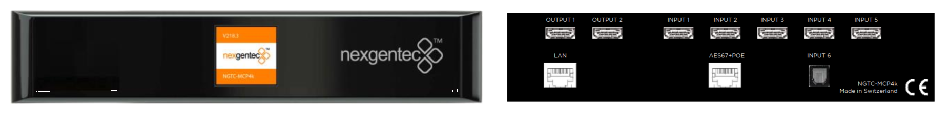
MCP4kR2

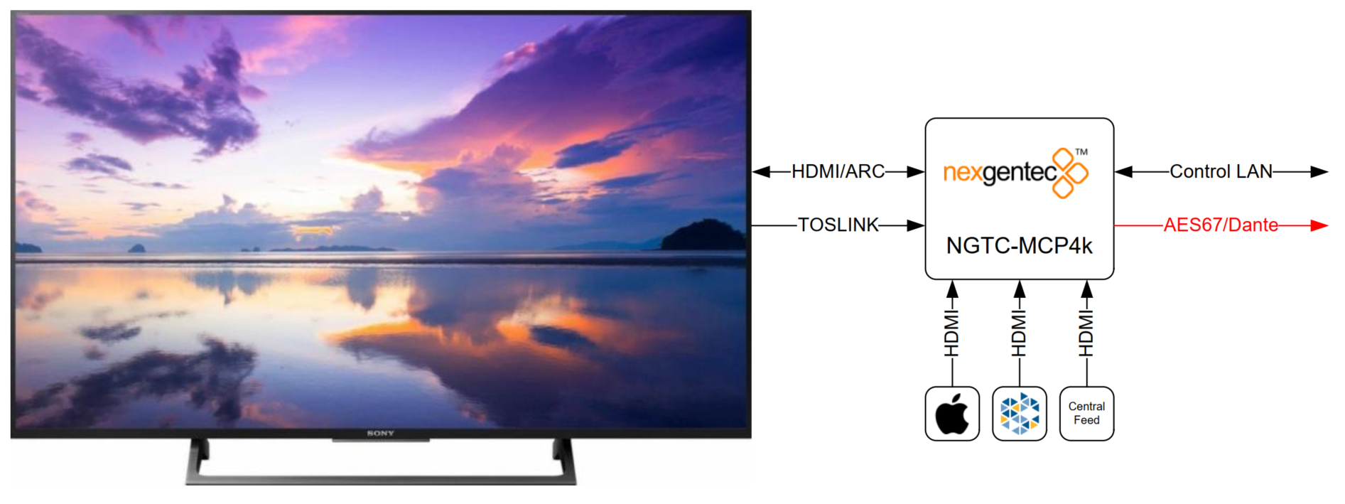
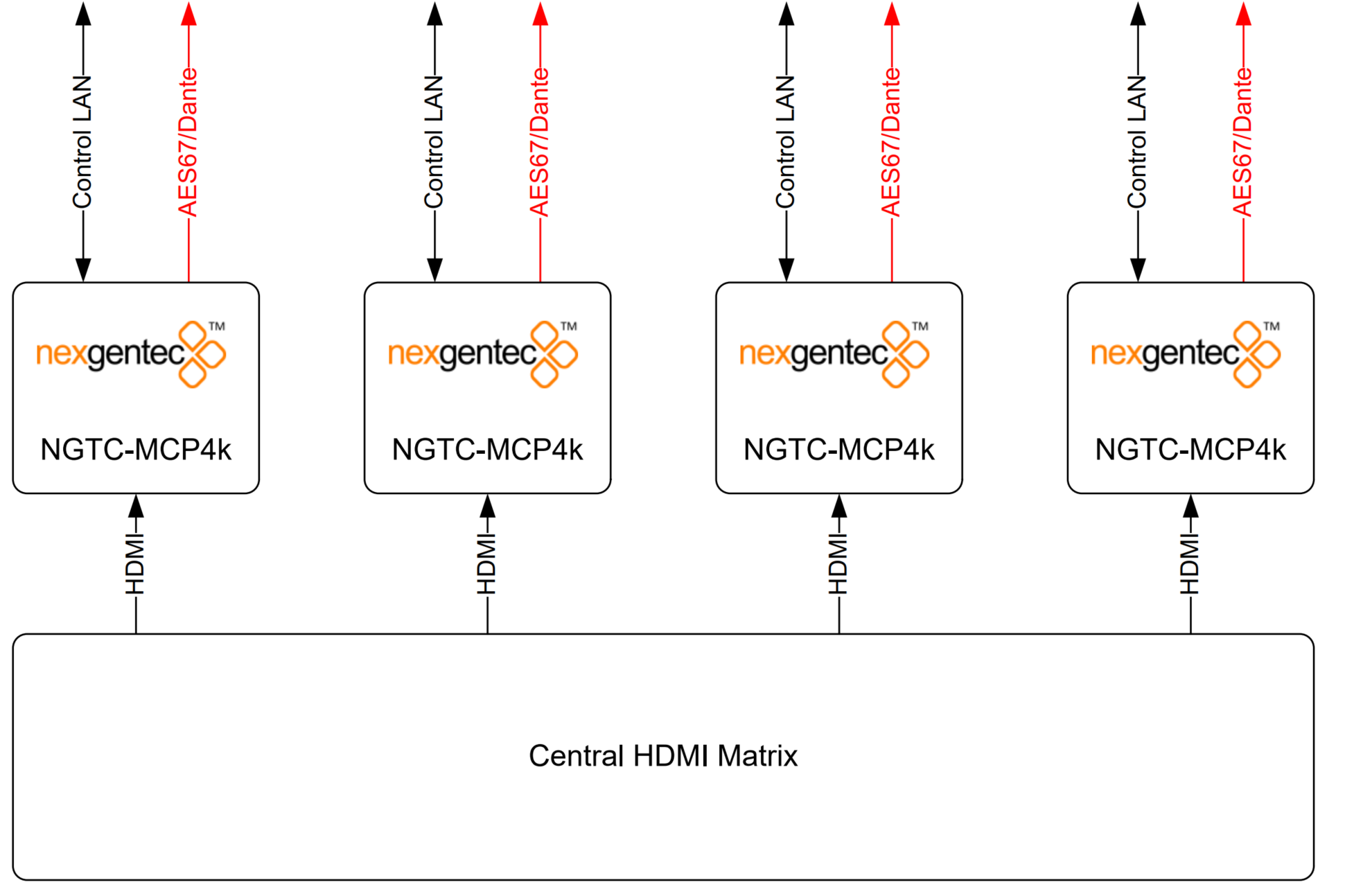
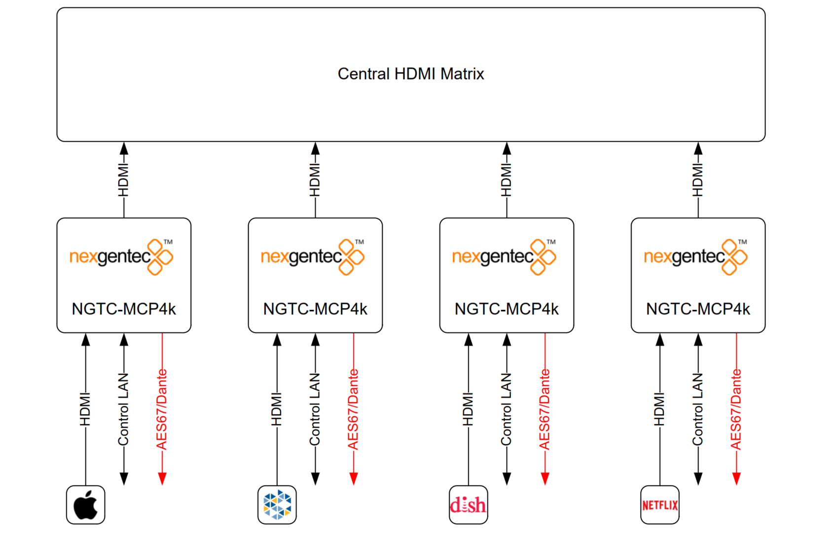
The NGTC-MCP4kR2 is an AES67 enabled multichannel audio processor for the Genesis Technologies™ audio distribution solution.

Picture Picture

Common Features

  • Decoding of all common digital audio formats, up to 8 channels
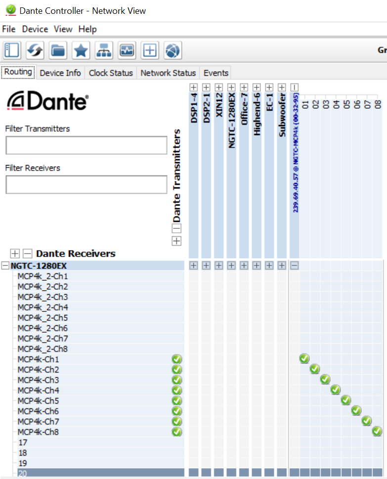
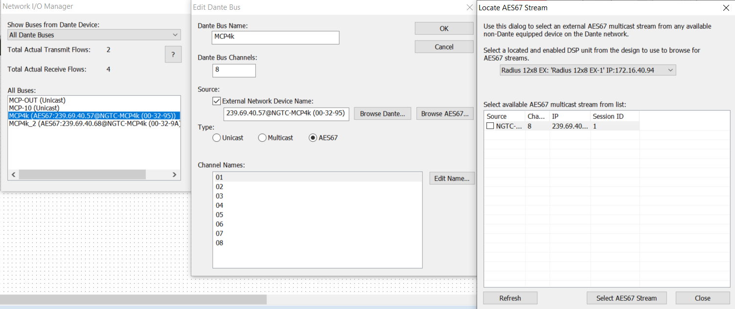
  • Outputs decoded channels on AES67 for audio processing by the NGTC digital signal processor or any AES67 enabled device.
  • Can be controller by any 3rd party control systems via the Control API.
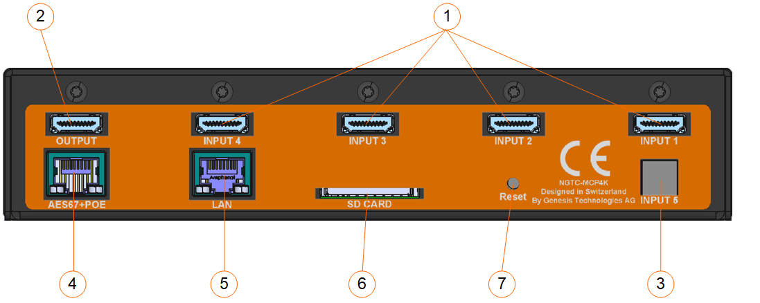
  • Powered by a POE on the AES67 port.
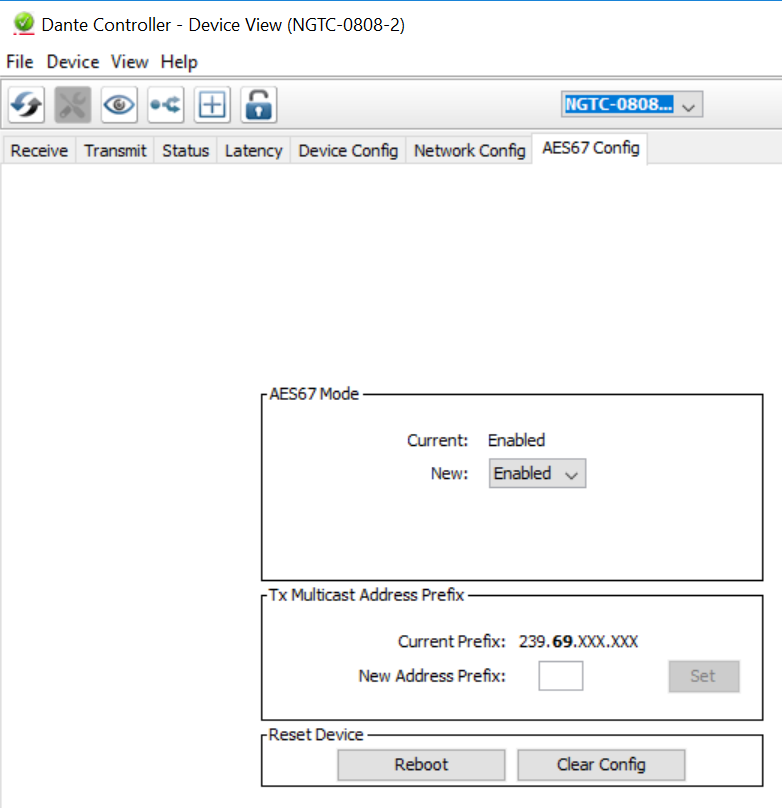
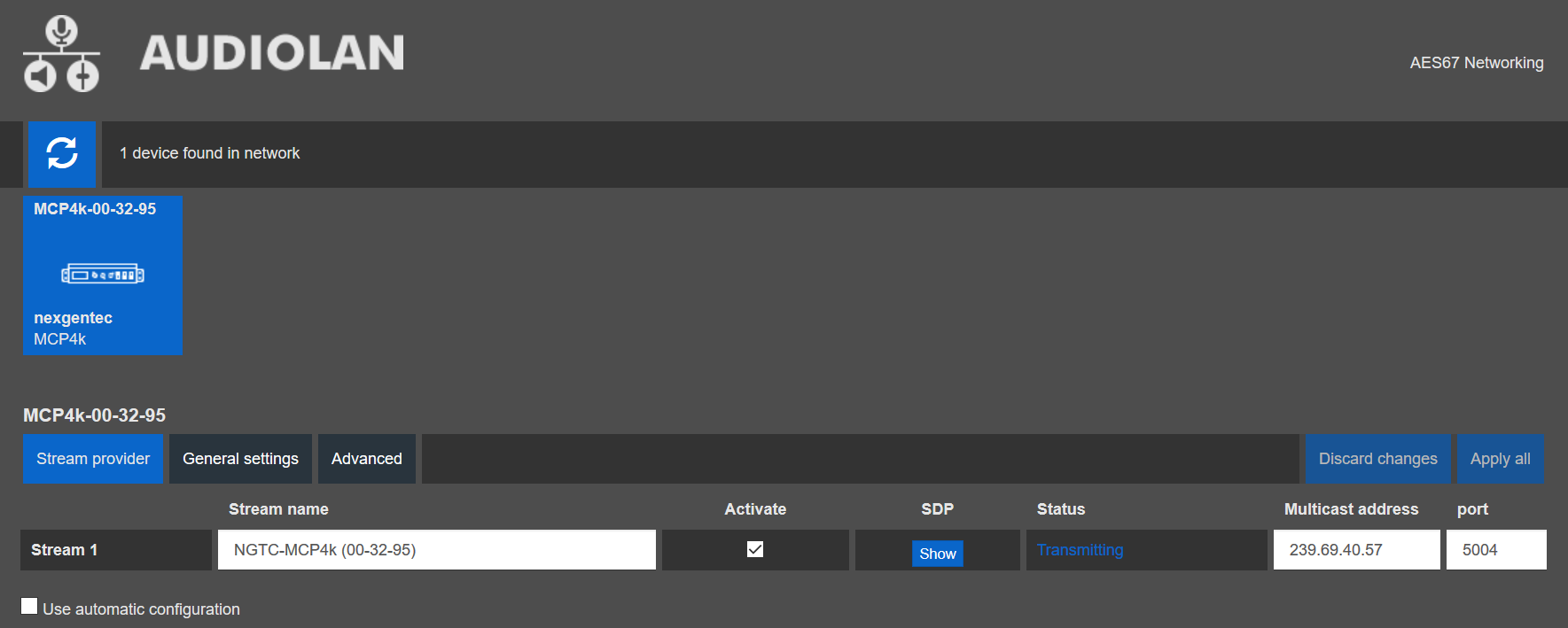
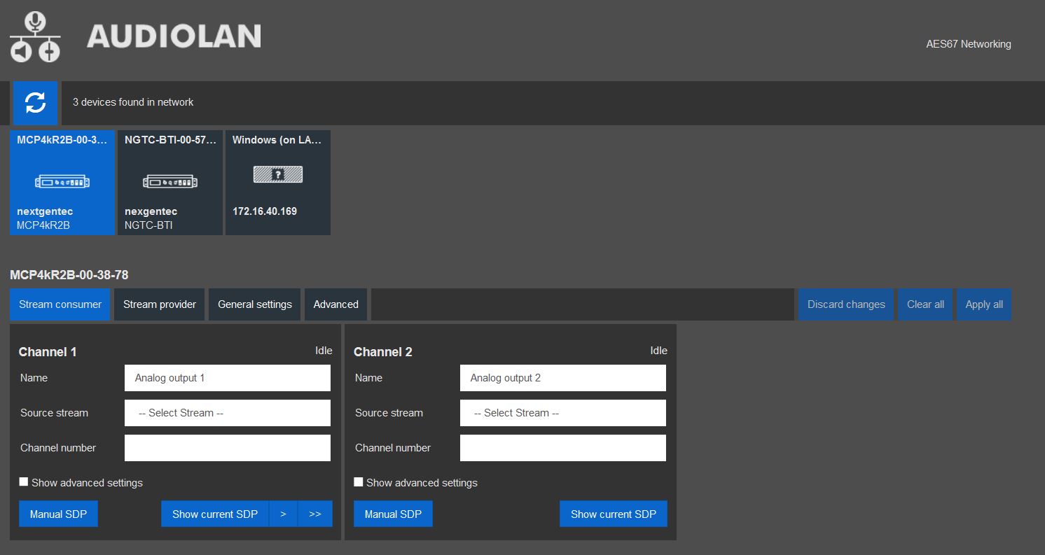
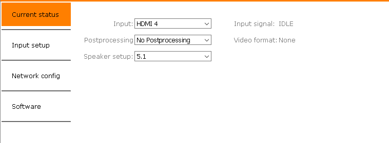
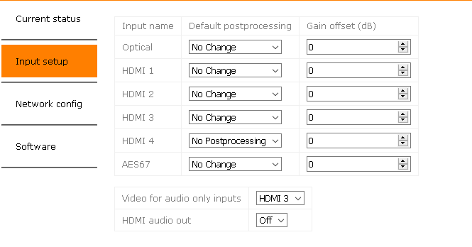
  • Web UI on the AES67 interface for AES67 related settings
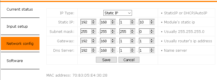
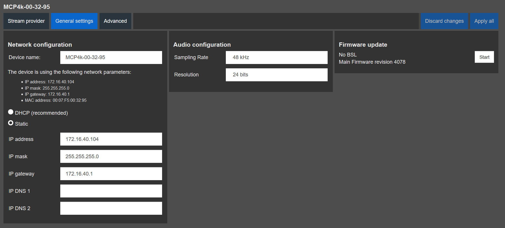
  • Control network port featuring the configuration web UI as well as the Control API.

Hardware Revision B (MCP4kR2B) addition Features

  • Ability to receive of a 2 channel AES audio stream that can be upmixed with ProLogic or DTS Neo.

Subsections of MCP4kR2

Application Note

Hardware

The NGTC-MCP4kR2 is an AES67 enabled multichannel audio processor for the Genesis TechnologiesTM audio distribution solution. It is capable of decoding all common digital audio formats, delivering up to 8 AES67 channels of audio for processing by the NGTC digital signal processors. It can be easily interfaced with 3rd party control systems via the control network port. The small form factor makes it very flexible in its application.

NGTC-MCP4kR2 front and back NGTC-MCP4kR2 front and back

Application 1 – In Room, Zone assigned

The MCP4kR2 audio processor will be placed in the zone. It will accept local sources, central feed and the audio return from the TV (ARC,TOSLINK). The unit will decode, post process and sent out 8 discrete channels via AES67 to the audio network. The bass management, time alignment and channel mapping will be done in the DSP’s for maximum flexibility and performance. To have in the master zone a full 7.1 system while the master bath and dressing may run 2.0 or 1.0 no more an issue. The NGTC DSP super modules by Genesis TechnologiesTM enable efficient design and deployment of NGTC AVOIP systems, featuring the highest levels of functionality and performance.

Picture Picture

Application 2 – In Rack, Zone assigned

The MCP4kR2 audio processor will be placed in the rack and does accept the feed from the central matrix. Each zone has its own MCP. The unit will decode, post process and sent out 8 discrete channels via AES67 to the audio network. The bass management, time alignment and channel mapping will be done in the DSP’s for maximum flexibility and performance. To have in the master zone a full 7.1 system while the master bath and dressing may run 2.0 or 1.0 no more an issue. The NGTC DSP super modules by Genesis TechnologiesTM enable efficient design and deployment of NGTC AVOIP systems, featuring the highest levels of functionality and performance.

Picture Picture

Application 3 – In Rack, Source assigned

The MCP4kR2 audio processor will be placed in the rack, connected to each source and the output of the processor will run into the central matrix. Audio and Video will be separated from the beginning. The MCP4k will decode, post process and sent out 8 discrete channels via AES67 to the audio network. The bass management, time alignment and channel mapping will be done in the DSP’s for maximum flexibility and performance. To have in the master zone a full 7.1 system while the master bath and dressing may run 2.0 or 1.0 no more an issue. The NGTC DSP super modules by Genesis TechnologiesTM enable efficient design and deployment of NGTC AVOIP systems, featuring the highest levels of functionality and performance.

Picture Picture

Installation

Test

Picture Picture

1.) HDMI inputs
2.) HDMI output
3.) Toslink digital input
4.) AES67 network interface (POE) – please use UTP cabling
5.) Control network interface – please use UTP cabling
6.) Service interface, not for use
7.) Reset button

Note

All connections to the NGTC-MCP4kR2 should be made before power is applied

• Attach any multimedia sources that will be used, to the inputs
• Attach the LAN network port to the control network switch, using an UTP CAT-5 cable
• Attach the AES67 network port to the AES67/Dante POE network switch, using an UTP CAT-5 cable.

Info

To reset the control network address (IP) long press (5s) the reset button on the back

Configuration

Setup interoperability between MCP4kR2 and Dante devices

Caution

AES67 interoperability settings are required for every Dante device that should receive a AES67 stream

To enable your Dante devices to receive an AES67 stream, AES67 interoperability must be enabled. This is done by using Audinate’s Dante Controller, which can be obtained from the Audinate website or any other manufacturer specific software tool.

In Dante controller all your Dante devices that are connected to the network will show up automatically.

  1. Start the Dante Controller Software and wait for it to be synchronized with the network
  2. Select the “device info” tab in the software
  3. Double click on the DSP you would like to configure for AES67, a new window will open
  4. Select the “AES67 config” tab
  5. Enable AES67 mode and make a note of the Tx multicast prefix. You will need this number later, even if you are not using the DSP as a transmitter. This must be the same for all DSP’s that are ready for AES67.
  6. Reboot the Dante device
  7. This needs to be done with every Dante device that will receive an AES67 stream

Picture Picture

Subsections of Configuration

Control Network Setup

Control Network Address Setup

The setup of the control network of the MCP4kR2 will be done via it’s Web UI. It is self-explaining

Info

By default the interface is set to DHCP

It is visible on the front display of the unit

Please make sure your computer network address is in the same network range to access the setup pages

Picture Picture

Refer to the MAC address if multiple MCP’s are in the network to identify the right unit. The MAC address is also printed on each units top cover

Info

To reset the control network address (IP) long press (5s) the reset button on the back

AES67 Network Setup (Audiolan)

AES67 Network Address Setup

Caution

There are two methods to configure AES67, depending on the AES67 daughter board in the MCP4KR2. Refer to the following instructions to configure it with the AudioGrid controller, especially if the setup provided below does not work for you.

To configure the AES67 network address use the built in Audiolan web UI. Your PC needs to be connected to the AES67 network and have its addressing set in the same IP range.

Info

By default the AES67 network interface is set to the static IP address (192.168.4.233)

Caution

To avoid an IP conflicts, connect one device after another and change each units IP to a different one

Note

Avoid any special characters and spaces in the device name

  1. Open a browser and enter the devices AES67 network address in the address bar, press enter
  2. Select the “General settings” tab in the web UI to change the devices IP address
  3. The NGTC-MCP4kR2 should have an IP and Subnet address in the same range as the Dante devices
  4. Apply all settings and reboot the device

Picture Picture

AES67 Stream Address Setup

Caution

The AES67 stream of each device needs to be configured to be received by the Dante/AES67 devices

Note

Avoid any special characters and spaces in the stream name

  1. Open a browser and enter the devices AES67 network address in the address bar, press enter
  2. Select the “Stream provider” tab in the web UI and uncheck the “Use automatic configuration” checkbox
  3. Make sure that the first 2 octets matches the Multicast Address Prefix given in the Dante Controller (239.69.xxx.xxx in the example below). Set the last 2 octets to unique values. always avoid duplicated IP addresses. Best practice is to set them to the same value as the last 2 octets of the AES67 network address
  4. Make sure that the “Activate” checkbox for the stream is checked
  5. Select the “Advanced” tab and ensure that the SAP browsing is enabled

Picture Picture

AES67 Receiving Stream Setup*

  1. Open a browser and enter the devices AES67 network address in the address bar, press enter
  2. Select the “Stream consumer” tab in the web UI and insert the AES Channel information for Channel 1 and Channel 2.

Picture Picture

*Hardware revision B (MCP4kR2B) only

AES67 Network Setup (AudioGrid)

Caution

There are two methods to configure AES67, depending on the AES67 daughter board in the MCP4KR2. Refer to the following instructions to configure it using the Audiolan Integrated website, especially if the setup provided below does not work for you.

To configure the AES67 download latest generation Audio Grid Controller Software. Your PC needs to be connected to the AES67 network and have its addressing set in the same IP range.

AudioGridController

AES67 Network Address Setup

Start the software and go to the “Device Config” tab

  1. Select the device to be configured
  2. Enter “IP Address” and “Subnet Mask”
  3. Hit “Apply”

AES67 Stream Address Setup

Caution

The AES67 stream of each device needs to be configured to be received by the Dante/AES67 devices

Start the software and go to the “Device Config” tab

  1. Select the device to be configured
  2. Select “Create / Delete” in the “Multicst flow” selection

Picture Picture

  1. In the Multicast flow config, click on “AG” first and then on “AES67”. Next, select the “Manual IP and Port” option.
  2. You can set your desired multicast IP. Typically in combination with Dante Audio products, the multicast IP starts with “239.69.”, port 5004.
  3. Select the channels that should be multicast.
  4. Click on “Create”.

Picture Picture

Audio Routing using Audinate’s Dante Controller

Global site parameters

Natively the audio routing can be done by using Audinate’s Dante Controller in case if its not auto configured by the DSP’s management software. In Dante Controller all your Dante and AES67 devices that are connected to the network will show up automatically.

The MCP4kR2 will be shown at the ‘‘Dante Transmitters’’ part, using its multicast address@hostname-HH-HH-HH where ‘‘HH-HH-HH’’ are the last three bytes of the devices MAC address.

Channel assignment

  • Make the audio connections in the Dante controller

Picture Picture

Audio Routing using Symnet Composer

In case of NGTC DSP hardware, the audio routing is done by using the Symetrix Symnet Composer. Please make sure all your Dante and AES67 devices that are connected to the network and are online. You might check this using Dante Controller.

Channel assignment

Create a 8 channel network AES67 receive module:

  1. In “Tools” open “Network I/O Manager”
  2. Select the corresponding bus and select “Edit Dante Bus”
  3. Check “External Network Device Name” and Browse AES67
  4. Pick the stream and Select AES67 Stream
  5. Insert the stream receiving module in the DSP’s configuration and connects its audio connections

Picture Picture

This will connect the MCP4kR2 AES67 stream to the DSP while going online. There is no need to use the Dante Controller to do the connection.

Audio Setup

Audio Configuration

The current input, post processing and specker setup can be set via WebUI on the control network interface. All audio settings can be overwritten on the fly by the control protocol

Speaker Setup

Available speaker Setup:

  • 2.0
  • 2.1
  • 5.1
  • 7.1

Post processing

Available post processing:

  • None/direct
  • PROLOGIC
  • PROLOGIC II MUSIC
  • PROLOGIC II MOVIE
  • DTS NEO6 MUSIC
  • DTS NEO6 CINEMA

Current settings

Picture Picture

Preset settings

Picture Picture

These settings are recalled each time the input is selected

  • Gain offset (dB) and Default Postprosessing: On each input a post processing preset and a gain offset can be defined.
  • AES67 Input: Ability to switch input to the 2 channel AES67 input stream.*
  • Video for audio only inputs: On use of an audio only input (optical or AES67) video will be switched to this input.*
  • HDMI audio out: Enables/Disables the the audio signal on the HDMI output.*

*Hardware revision B (MCP4kR2B) only

Control API

Definitions

This section describes the communication protocol between the control system and the MCP4kR2

Connection TCP (NGTC-MCP4kR2 is server), Port 84
Command Format !Command(parameter)<cr> or !Command?<cr>
Caution

All commands start with “!”, end with <CR>
<CR>stands for “carriage return”, corresponding hex is 0x0D
<LF> stands for “line feed”, corresponding hex is 0x0A
If a command has a parameter, the parameter is in between “(” “)”
If a command is a “set” command “(parameter)”, then there is no reply
If a command is a “request” command “?”,the value will be in the reply

Caution

Send only one command at the time and wait for reply before sending the next one


Ping

Communication Command Parameter Example
Request !PING<CR>
Reply !PONG<CR><LF>

Verbosity

Select verbosity

Communication Command Parameter Example
Request !VERB(Parameter)<CR>
0: (default) Only send requested datal
1: Send requested data plus status changes
2: Send requested data, status and echo commands
!VERB(2)<CR>
Reply

Request active verbosity

Communication Command Parameter Example
Request !VERB?<CR>
!VERB?<CR>
Reply !VERB(2)<CR><LF>

Post processing

Select post processing

Communication Command Parameter Example
Request !POSTP(Parameter)<CR>
0: None
1: PROLOGIC
2: PROLOGIC II MUSIC
3: PROLOGIC II MOVIE
4: DTS NEO6 MUSIC
4: DTS NEO6 CINEMA
!POSTP(2)<CR>
Reply

Request active post processing number

Communication Command Parameter Example
Request !POSTP?<CR>
!POSTP?<CR>
Reply !POSTP(3)<CR><LF>

Request active post processing name

Communication Command Parameter Example
Request !POSTPNAME?<CR>
!POSTPNAME?<CR>
Reply !POSTPNAME(Music)<CR><LF>

Audio format

Request active audio format

Communication Command Parameter Example
Request !AUDIOSTATUS?<CR>
!AUDIOSTATUS?<CR>
Reply !AUDIOSTATUS(TRUEHD)<CR><LF>

HDMI audio output

Enable HDMI audio output

Communication Command Parameter Example
Request !HDMIAUDON<<CR>
!HDMIAUDON<<CR>
Reply

Disable HDMI audio output

Communication Command Parameter Example
Request !HDMIAUDOFF<<CR>
!HDMIAUDOFF<<CR>
Reply

Request HDMI audio output

Communication Command Parameter Example
Request !HDMIAUD?<CR>
!HDMIAUD<CR>
Reply !HDMIAUDOFF()<CR><LF>

Source

Select source

Communication Command Parameter Example
Request !SRC(Parameter)<CR>
0: Optical
1: HDMI 1
2: HDMI 2
3: HDMI 3
4: HDMI 4
5: AES67*
!SRC(3)<CR>
Reply

*Hardware revision B (MCP4kR2B) only

Request active source number

Communication Command Parameter Example
Request !SRC?<CR>
!SRC?<CR>
Reply !SRC(3)<CR><LF>

Request active source name

Communication Command Parameter Example
Request !SRCNAME?<<CR>
!SRCNAME?<<CR>
Reply !HDMI 3<CR><LF>

Select next source

Communication Command Parameter Example
Request !SRCUP?<<CR>
!SRCUP?<<CR>
Reply

Select previous source

Communication Command Parameter Example
Request !SRCDN?<<CR>
!SRCDN?<<CR>
Reply

Select video source for audio only input (optical or AES67)*

Communication Command Parameter Example
Request !OPTVID(Parameter)<CR>
0: No Input
1: HDMI 1
2: HDMI 2
3: HDMI 3
4: HDMI 4
!OPTVID(3)<CR>
Reply

*Hardware revision B (MCP4kR2B) only

Request active video source for audio only input (optical or AES67)*

Communication Command Parameter Example
Request !OPTVID?<CR>
!OPTVID?<CR>
Reply !SRC(3)<CR><LF>

*Hardware revision B (MCP4kR2B) only

Speaker setup

Select speaker setup

Communication Command Parameter Example
Request !SPKSETUP(Parameter)<CR>
2.0: 2ch, full range
2.1: 2ch, full range, LFE
5.1: 5ch, full range, LFE
7.1: 5ch, full range, LFE
!SPKSETUP(5.1)<<CR>
Reply

Request active speaker setup

Communication Command Parameter Example
Request !SPKSETUP?<CR>
!SPKSETUP?<CR>
Reply !SPKSETUP(5.1)<CR><LF>

Request video status

Communication Command Parameter Example
Request !VIDEOSTATUS?<CR>
!VIDEOSTATUS?<CR>
Reply !VIDEOSTATUS(2160p)<CR><LF>

Specifications

HDMI
Type HDMI 2.0/HDCP 2.2
Matrix 1 x 1 Input selector, no scaling
Digital Audio Input
Type TOSLINK
Format PCM, LPCM, DD, DTS up to 6 channels. 24Bit/96kHz Audio
Digital Audio Output
Type 8 channels, full range
Format Aes67
Audio Performance
Format PCM, LPCM, DD, DTS, Dolby True HD, DTS Master HD, DD+
EIN -115dBu
System THD+N <100dB, unweighted; 1kHz@+22dBu with 0dB gain
Freq. Response 20Hz – 20kHz, +/- 1dB
AES67 Network with WebUI
Physical Level Standard Ethernet
Connector Single RJ-45
Cable Quality CAT-5/6/7
Transmission Speed 100 Mbps Full Duplex
Control Network with WebUI
Physical Level Standard Ethernet
Connector Single RJ-45
Cable Quality CAT-5/6/7
Transmission Speed 100 Mbps Full Duplex
General
Power POE, 10W max
Total heat dissipation 20.00 BTU/hr
Operating temp 0°C – 60°C
Dimensions L: 250mm, W: 208mm, H:44mm
Compliance CE, ROHS

Audio Channel Assignment

Channel Assignment
1 Left Front
2 Right Front
3 Left Surround
4 Right Surround
5 Center Front
6 LFE
7 Left Rear
8 Right Rear
Step files

Accessories

Mounting

The MCP4kR2 is half rack width and one rack unit high. If positioned in the rack, it can be mounted the rack shelf that is available. A half rack filler panel is available as well.

Picture Picture

Picture Picture

Firmware

Firmware

Welcome to the Firmware section!

If you are not redirected automatically, click here.

Subsections of Firmware

Device

Device Firmware Updates

Firmware updates will be published on this site once a new release has passed all tests. To update download the latest version and upload it to the MCP4kR2

Picture Picture

Release notes:

mcp4k-1.0.6-8-g186ea03

  • Fixed audio drop outs

mcp4k_mcp4k-1.0.7-5-g39aa7b8;

  • Fixed audio drop outs using ATV
  • Fixed various HDMI issues
  • New hardware support

Audio Card

Audio Card Firmware Update

The latest generation of MCP4kR2 features an AES67 daughter board that fully supports AES67, ensuring compatibility with Dante™. Additionally, these devices have mDNS discovery enabled, allowing them to be detected in the Dante Controller, similar to a Dante product.

However, starting with Dante Controller V12, a pop-up message may appear indicating that unlicensed Dante™ products are being used. To address this, the new firmware will disable Dante™ discovery, and all R2 units will be recognized as AES67 devices.

Update to the Latest AES67 only Firmware Release

  1. Download the latest programmer and firmware files
  2. Unzip the firmware files (MCP4kR2B-FW_4102-4108.zip) into a folder.
  3. Run the updater tool (Fdt_factory1.63.exe). Note that the discovery function works for up to 10 units. If you have more units, use the IP address filter for efficient navigation.
  4. Open the FPGA firmware file with the updater tool (fpga_a408_4108.bit).
  5. Open the MCU firmware file with the updater tool (mcu_407d_4102.bin).

Picture Picture

  1. Update all units with the new MCU by clicking in the field MCU Upgrade.
  2. Update all units with the new FPGA by clicking in the field FPGA Upgrade.
  3. Select all updated units in the latest row for reboot.
  4. Click “Reboot”.
Notice

After the reboot, click “Refresh” to update the device list. If the devices appear as expected, you can proceed with the update process.

  1. Open the Initialize data file with the updater tool (MCP4kR2B-AES67.c).

Picture Picture

  1. Update all units with the new Init data fle by clicking in the field Init Data.
  2. Select all updated units in the latest row for reboot.
  3. Click “Reboot”.
Notice

After the reboot, you need to set the multicast address for AES67 to work. Use the Audio Grid Controller to do this.

Refer to the following instructions to configure it with the AudioGrid controller