tech docs
![]()
![]()
![]()
![]()
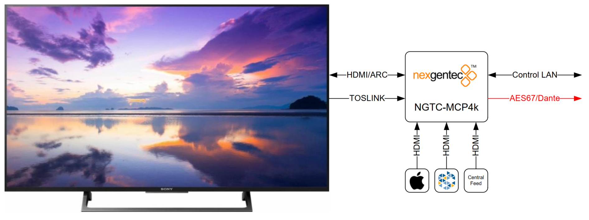
The NGTC-MCP4kR2 is an AES67 enabled multichannel audio processor for the Genesis Technologies™ audio distribution solution.

The NGTC-MCP4kR2 is an AES67 enabled multichannel audio processor for the Genesis TechnologiesTM audio distribution solution. It is capable of decoding all common digital audio formats, delivering up to 8 AES67 channels of audio for processing by the NGTC digital signal processors. It can be easily interfaced with 3rd party control systems via the control network port. The small form factor makes it very flexible in its application.

The MCP4kR2 audio processor will be placed in the zone. It will accept local sources, central feed and the audio return from the TV (ARC,TOSLINK). The unit will decode, post process and sent out 8 discrete channels via AES67 to the audio network. The bass management, time alignment and channel mapping will be done in the DSP’s for maximum flexibility and performance. To have in the master zone a full 7.1 system while the master bath and dressing may run 2.0 or 1.0 no more an issue. The NGTC DSP super modules by Genesis TechnologiesTM enable efficient design and deployment of NGTC AVOIP systems, featuring the highest levels of functionality and performance.
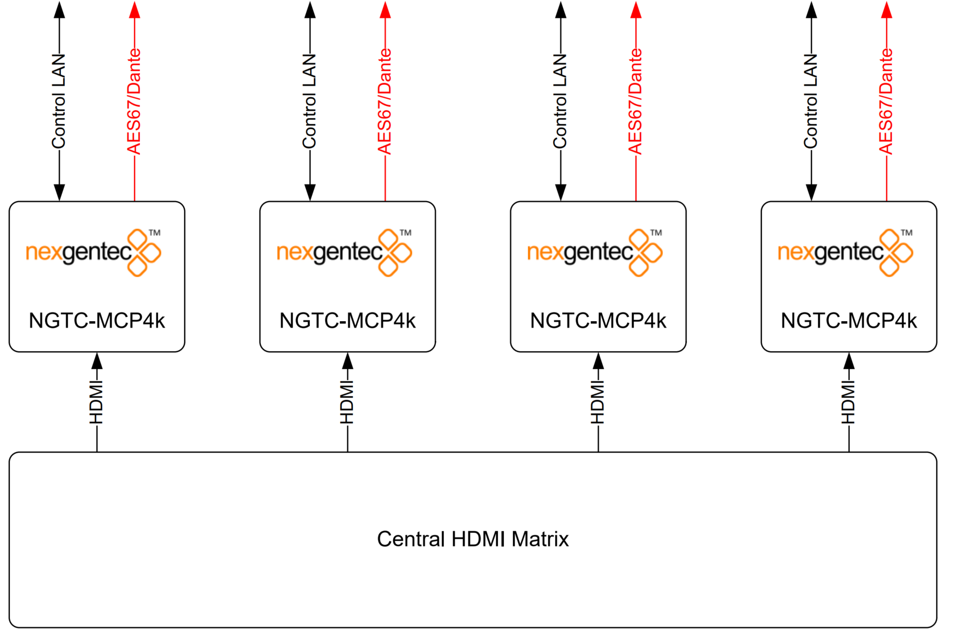
The MCP4kR2 audio processor will be placed in the rack and does accept the feed from the central matrix. Each zone has its own MCP. The unit will decode, post process and sent out 8 discrete channels via AES67 to the audio network. The bass management, time alignment and channel mapping will be done in the DSP’s for maximum flexibility and performance. To have in the master zone a full 7.1 system while the master bath and dressing may run 2.0 or 1.0 no more an issue. The NGTC DSP super modules by Genesis TechnologiesTM enable efficient design and deployment of NGTC AVOIP systems, featuring the highest levels of functionality and performance.
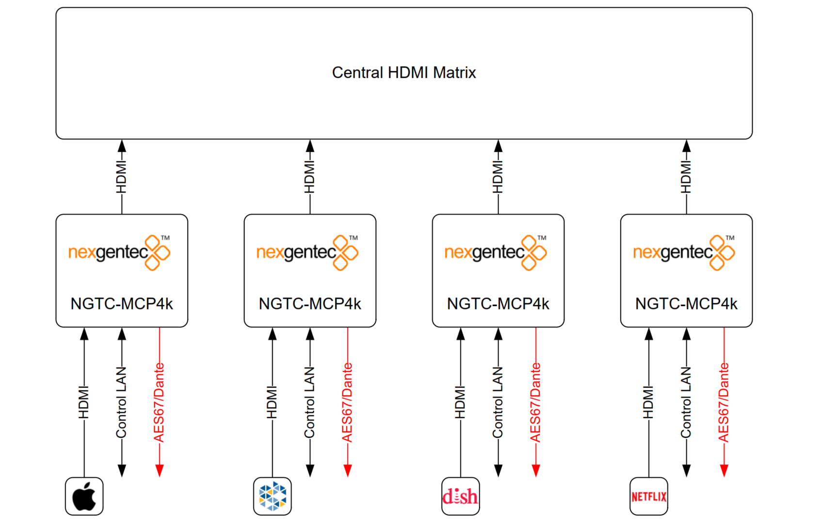
The MCP4kR2 audio processor will be placed in the rack, connected to each source and the output of the processor will run into the central matrix. Audio and Video will be separated from the beginning. The MCP4k will decode, post process and sent out 8 discrete channels via AES67 to the audio network. The bass management, time alignment and channel mapping will be done in the DSP’s for maximum flexibility and performance. To have in the master zone a full 7.1 system while the master bath and dressing may run 2.0 or 1.0 no more an issue. The NGTC DSP super modules by Genesis TechnologiesTM enable efficient design and deployment of NGTC AVOIP systems, featuring the highest levels of functionality and performance.
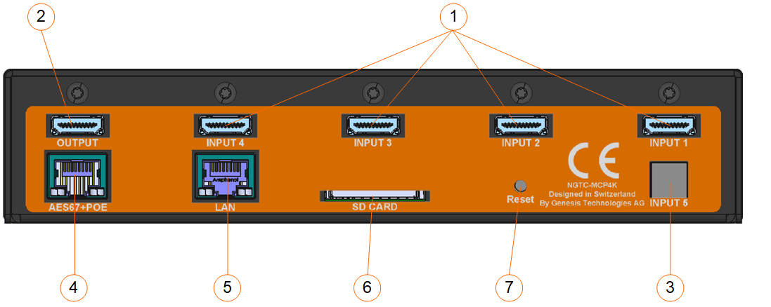
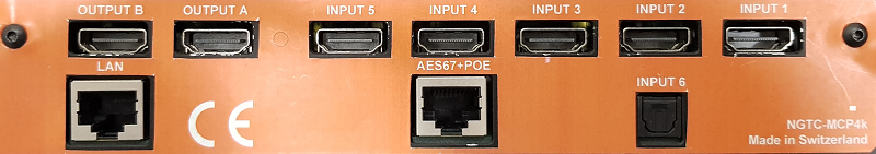
1.) HDMI inputs
2.) HDMI output
3.) Toslink digital input
4.) AES67 network interface (POE) – please use UTP cabling
5.) Control network interface – please use UTP cabling
6.) Service interface, not for use
7.) Reset button
All connections to the NGTC-MCP4kR2 should be made before power is applied
• Attach any multimedia sources that will be used, to the inputs
• Attach the LAN network port to the control network switch, using an UTP CAT-5 cable
• Attach the AES67 network port to the AES67/Dante POE network switch, using an UTP CAT-5 cable.
To reset the control network address (IP) long press (5s) the reset button on the back
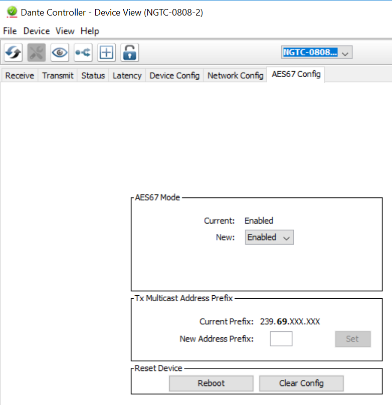
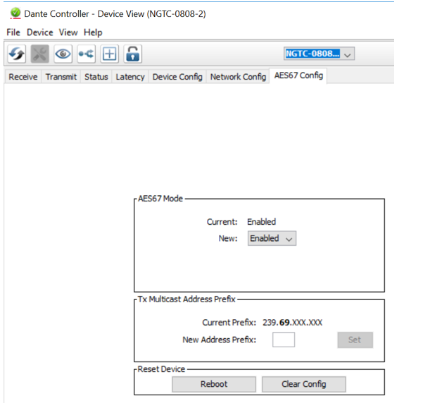
AES67 interoperability settings are required for every Dante device that should receive a AES67 stream
To enable your Dante devices to receive an AES67 stream, AES67 interoperability must be enabled. This is done by using Audinate’s Dante Controller, which can be obtained from the Audinate website or any other manufacturer specific software tool.
In Dante controller all your Dante devices that are connected to the network will show up automatically.
The setup of the control network of the MCP4kR2 will be done via it’s Web UI. It is self-explaining
By default the interface is set to DHCP
It is visible on the front display of the unit
Please make sure your computer network address is in the same network range to access the setup pages
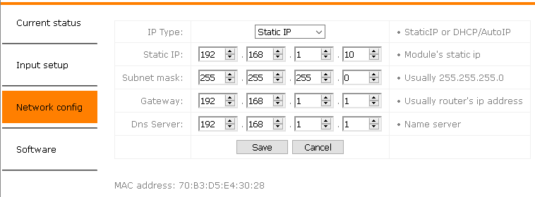
Refer to the MAC address if multiple MCP’s are in the network to identify the right unit. The MAC address is also printed on each units top cover
To reset the control network address (IP) long press (5s) the reset button on the back
There are two methods to configure AES67, depending on the AES67 daughter board in the MCP4KR2. Refer to the following instructions to configure it with the AudioGrid controller, especially if the setup provided below does not work for you.
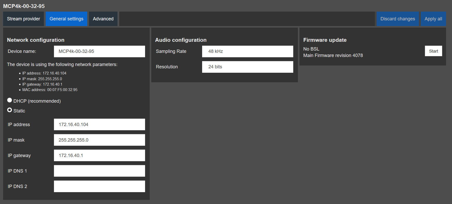
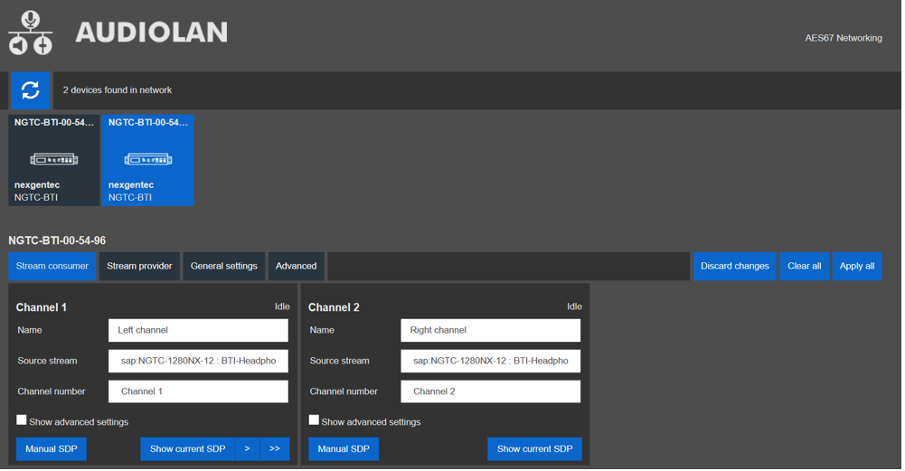
To configure the AES67 network address use the built in Audiolan web UI. Your PC needs to be connected to the AES67 network and have its addressing set in the same IP range.
By default the AES67 network interface is set to the static IP address (192.168.4.233)
To avoid an IP conflicts, connect one device after another and change each units IP to a different one
Avoid any special characters and spaces in the device name
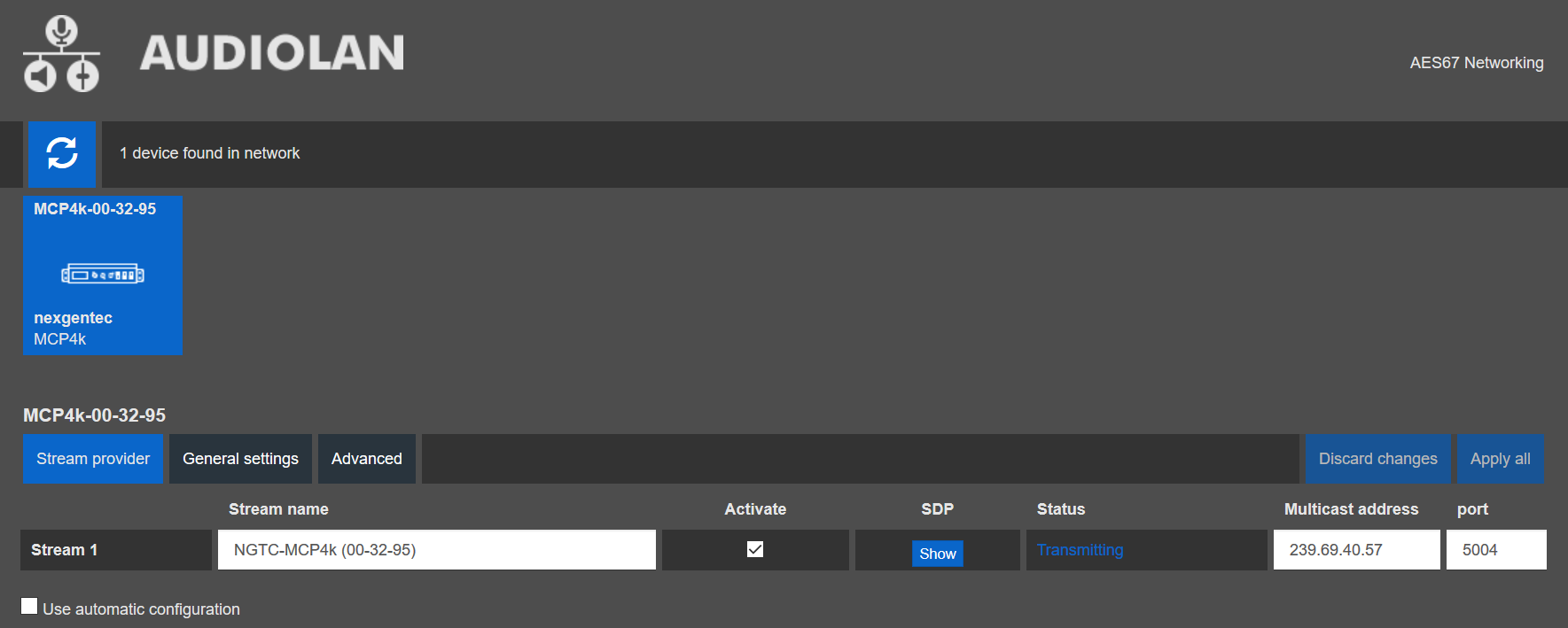
The AES67 stream of each device needs to be configured to be received by the Dante/AES67 devices
Avoid any special characters and spaces in the stream name
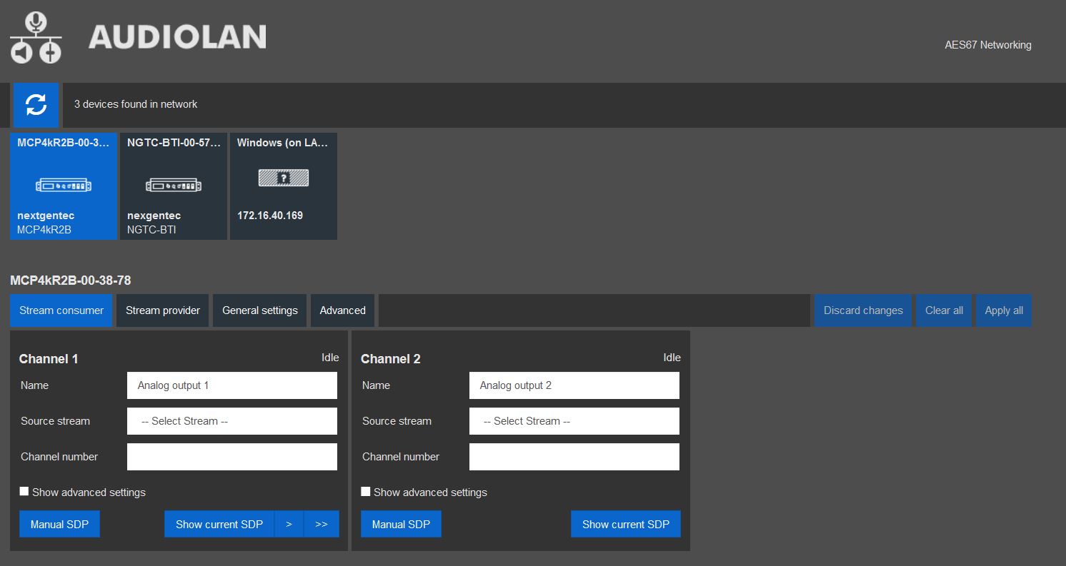
*Hardware revision B (MCP4kR2B) only
There are two methods to configure AES67, depending on the AES67 daughter board in the MCP4KR2. Refer to the following instructions to configure it using the Audiolan Integrated website, especially if the setup provided below does not work for you.
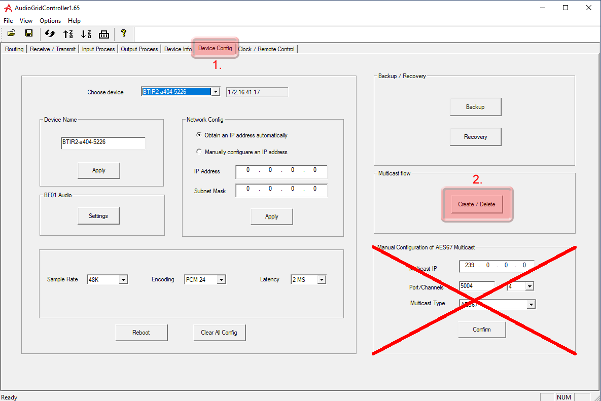
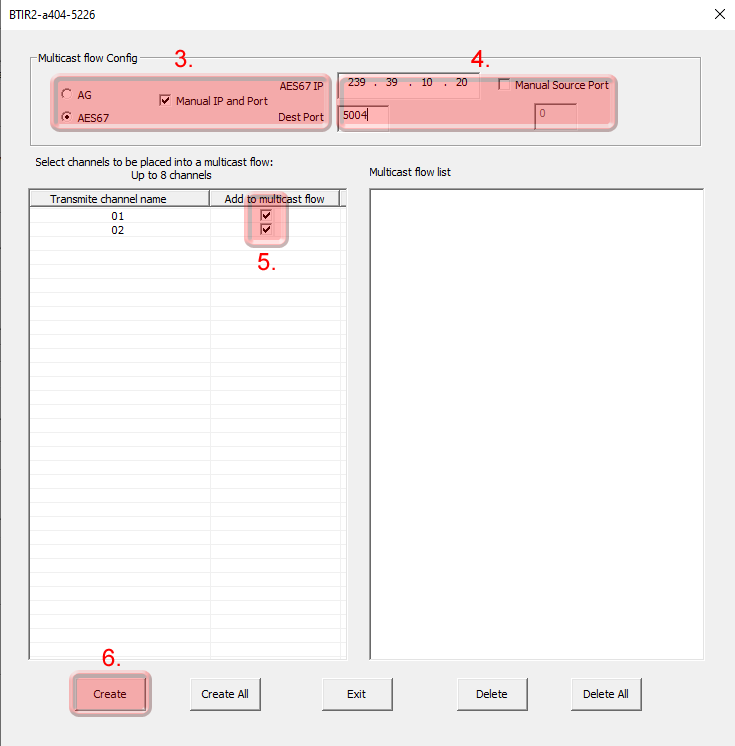
To configure the AES67 download latest generation Audio Grid Controller Software. Your PC needs to be connected to the AES67 network and have its addressing set in the same IP range.
Start the software and go to the “Device Config” tab
The AES67 stream of each device needs to be configured to be received by the Dante/AES67 devices
Start the software and go to the “Device Config” tab
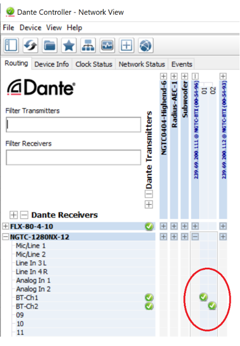
Natively the audio routing can be done by using Audinate’s Dante Controller in case if its not auto configured by the DSP’s management software. In Dante Controller all your Dante and AES67 devices that are connected to the network will show up automatically.
The MCP4kR2 will be shown at the ‘‘Dante Transmitters’’ part, using its multicast address@hostname-HH-HH-HH where ‘‘HH-HH-HH’’ are the last three bytes of the devices MAC address.
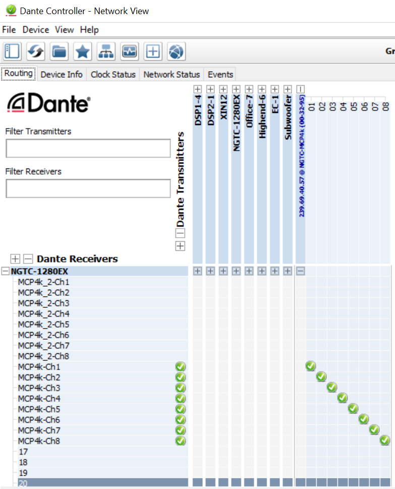
In case of NGTC DSP hardware, the audio routing is done by using the Symetrix Symnet Composer. Please make sure all your Dante and AES67 devices that are connected to the network and are online. You might check this using Dante Controller.
Create a 8 channel network AES67 receive module:
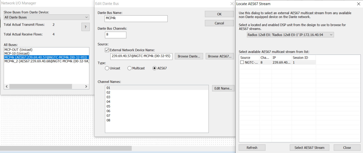
This will connect the MCP4kR2 AES67 stream to the DSP while going online. There is no need to use the Dante Controller to do the connection.
The current input, post processing and specker setup can be set via WebUI on the control network interface. All audio settings can be overwritten on the fly by the control protocol
Available speaker Setup:
Available post processing:
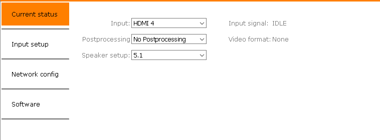
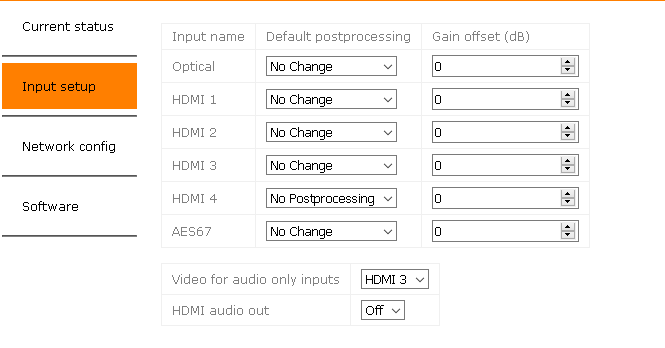
These settings are recalled each time the input is selected
*Hardware revision B (MCP4kR2B) only
This section describes the communication protocol between the control system and the MCP4kR2
| Connection | TCP (NGTC-MCP4kR2 is server), Port 84 |
| Command Format | !Command(parameter)<cr> or !Command?<cr> |
All commands start with “!”, end with <CR>
<CR>stands for “carriage return”, corresponding hex is 0x0D
<LF> stands for “line feed”, corresponding hex is 0x0A
If a command has a parameter, the parameter is in between “(” “)”
If a command is a “set” command “(parameter)”, then there is no reply
If a command is a “request” command “?”,the value will be in the reply
Send only one command at the time and wait for reply before sending the next one
| Communication | Command | Parameter | Example |
|---|---|---|---|
| Request | !PING<CR> |
||
| Reply | !PONG<CR><LF> |
| Communication | Command | Parameter | Example |
|---|---|---|---|
| Request | !VERB(Parameter)<CR> |
||
| 0: (default) Only send requested datal | |||
| 1: Send requested data plus status changes | |||
| 2: Send requested data, status and echo commands | |||
!VERB(2)<CR> |
|||
| Reply |
| Communication | Command | Parameter | Example |
|---|---|---|---|
| Request | !VERB?<CR> |
||
!VERB?<CR> |
|||
| Reply | !VERB(2)<CR><LF> |
| Communication | Command | Parameter | Example |
|---|---|---|---|
| Request | !POSTP(Parameter)<CR> |
||
| 0: None | |||
| 1: PROLOGIC | |||
| 2: PROLOGIC II MUSIC | |||
| 3: PROLOGIC II MOVIE | |||
| 4: DTS NEO6 MUSIC | |||
| 4: DTS NEO6 CINEMA | |||
!POSTP(2)<CR> |
|||
| Reply |
| Communication | Command | Parameter | Example |
|---|---|---|---|
| Request | !POSTP?<CR> |
||
!POSTP?<CR> |
|||
| Reply | !POSTP(3)<CR><LF> |
| Communication | Command | Parameter | Example |
|---|---|---|---|
| Request | !POSTPNAME?<CR> |
||
!POSTPNAME?<CR> |
|||
| Reply | !POSTPNAME(Music)<CR><LF> |
| Communication | Command | Parameter | Example |
|---|---|---|---|
| Request | !AUDIOSTATUS?<CR> |
||
!AUDIOSTATUS?<CR> |
|||
| Reply | !AUDIOSTATUS(TRUEHD)<CR><LF> |
| Communication | Command | Parameter | Example |
|---|---|---|---|
| Request | !HDMIAUDON<<CR> |
||
!HDMIAUDON<<CR> |
|||
| Reply |
| Communication | Command | Parameter | Example |
|---|---|---|---|
| Request | !HDMIAUDOFF<<CR> |
||
!HDMIAUDOFF<<CR> |
|||
| Reply |
| Communication | Command | Parameter | Example |
|---|---|---|---|
| Request | !HDMIAUD?<CR> |
||
!HDMIAUD<CR> |
|||
| Reply | !HDMIAUDOFF()<CR><LF> |
| Communication | Command | Parameter | Example |
|---|---|---|---|
| Request | !SRC(Parameter)<CR> |
||
| 0: Optical | |||
| 1: HDMI 1 | |||
| 2: HDMI 2 | |||
| 3: HDMI 3 | |||
| 4: HDMI 4 | |||
| 5: AES67* | |||
!SRC(3)<CR> |
|||
| Reply |
*Hardware revision B (MCP4kR2B) only
| Communication | Command | Parameter | Example |
|---|---|---|---|
| Request | !SRC?<CR> |
||
!SRC?<CR> |
|||
| Reply | !SRC(3)<CR><LF> |
| Communication | Command | Parameter | Example |
|---|---|---|---|
| Request | !SRCNAME?<<CR> |
||
!SRCNAME?<<CR> |
|||
| Reply | !HDMI 3<CR><LF> |
| Communication | Command | Parameter | Example |
|---|---|---|---|
| Request | !SRCUP?<<CR> |
||
!SRCUP?<<CR> |
|||
| Reply |
| Communication | Command | Parameter | Example |
|---|---|---|---|
| Request | !SRCDN?<<CR> |
||
!SRCDN?<<CR> |
|||
| Reply |
| Communication | Command | Parameter | Example |
|---|---|---|---|
| Request | !OPTVID(Parameter)<CR> |
||
| 0: No Input | |||
| 1: HDMI 1 | |||
| 2: HDMI 2 | |||
| 3: HDMI 3 | |||
| 4: HDMI 4 | |||
!OPTVID(3)<CR> |
|||
| Reply |
*Hardware revision B (MCP4kR2B) only
| Communication | Command | Parameter | Example |
|---|---|---|---|
| Request | !OPTVID?<CR> |
||
!OPTVID?<CR> |
|||
| Reply | !SRC(3)<CR><LF> |
*Hardware revision B (MCP4kR2B) only
| Communication | Command | Parameter | Example |
|---|---|---|---|
| Request | !SPKSETUP(Parameter)<CR> |
||
| 2.0: 2ch, full range | |||
| 2.1: 2ch, full range, LFE | |||
| 5.1: 5ch, full range, LFE | |||
| 7.1: 5ch, full range, LFE | |||
!SPKSETUP(5.1)<<CR> |
|||
| Reply |
| Communication | Command | Parameter | Example |
|---|---|---|---|
| Request | !SPKSETUP?<CR> |
||
!SPKSETUP?<CR> |
|||
| Reply | !SPKSETUP(5.1)<CR><LF> |
| Communication | Command | Parameter | Example |
|---|---|---|---|
| Request | !VIDEOSTATUS?<CR> |
||
!VIDEOSTATUS?<CR> |
|||
| Reply | !VIDEOSTATUS(2160p)<CR><LF> |
| HDMI | |
| Type | HDMI 2.0/HDCP 2.2 |
| Matrix | 1 x 1 Input selector, no scaling |
| Digital Audio Input | |
| Type | TOSLINK |
| Format | PCM, LPCM, DD, DTS up to 6 channels. 24Bit/96kHz Audio |
| Digital Audio Output | |
| Type | 8 channels, full range |
| Format | Aes67 |
| Audio Performance | |
| Format | PCM, LPCM, DD, DTS, Dolby True HD, DTS Master HD, DD+ |
| EIN | -115dBu |
| System THD+N | <100dB, unweighted; 1kHz@+22dBu with 0dB gain |
| Freq. Response | 20Hz – 20kHz, +/- 1dB |
| AES67 Network with WebUI | |
| Physical Level | Standard Ethernet |
| Connector | Single RJ-45 |
| Cable Quality | CAT-5/6/7 |
| Transmission Speed | 100 Mbps Full Duplex |
| Control Network with WebUI | |
| Physical Level | Standard Ethernet |
| Connector | Single RJ-45 |
| Cable Quality | CAT-5/6/7 |
| Transmission Speed | 100 Mbps Full Duplex |
| General | |
| Power | POE, 10W max |
| Total heat dissipation | 20.00 BTU/hr |
| Operating temp | 0°C – 60°C |
| Dimensions | L: 250mm, W: 208mm, H:44mm |
| Compliance | CE, ROHS |
| Channel | Assignment |
|---|---|
| 1 | Left Front |
| 2 | Right Front |
| 3 | Left Surround |
| 4 | Right Surround |
| 5 | Center Front |
| 6 | LFE |
| 7 | Left Rear |
| 8 | Right Rear |
The MCP4kR2 is half rack width and one rack unit high. If positioned in the rack, it can be mounted the rack shelf that is available. A half rack filler panel is available as well.


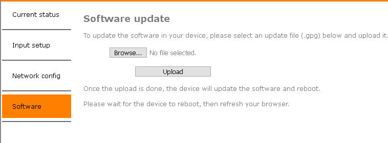
Welcome to the Firmware section!
If you are not redirected automatically, click here.
Firmware updates will be published on this site once a new release has passed all tests. To update download the latest version and upload it to the MCP4kR2
mcp4k-1.0.6-8-g186ea03
mcp4k_mcp4k-1.0.7-5-g39aa7b8;
The latest generation of MCP4kR2 features an AES67 daughter board that fully supports AES67, ensuring compatibility with Dante™. Additionally, these devices have mDNS discovery enabled, allowing them to be detected in the Dante Controller, similar to a Dante product.
However, starting with Dante Controller V12, a pop-up message may appear indicating that unlicensed Dante™ products are being used. To address this, the new firmware will disable Dante™ discovery, and all R2 units will be recognized as AES67 devices.
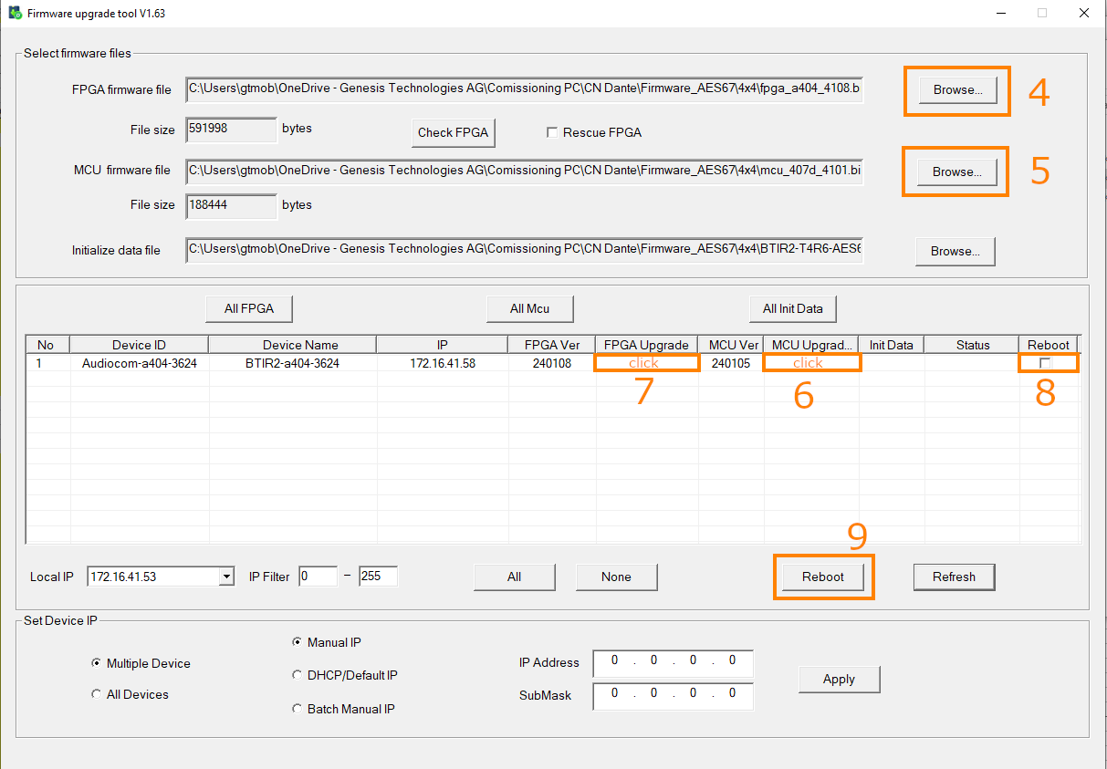
After the reboot, click “Refresh” to update the device list. If the devices appear as expected, you can proceed with the update process.
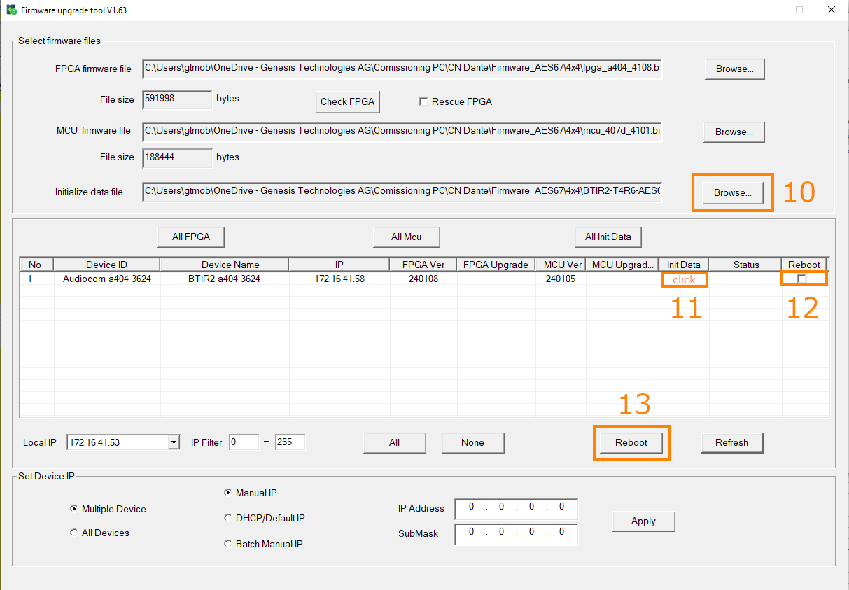
After the reboot, you need to set the multicast address for AES67 to work. Use the Audio Grid Controller to do this.
Refer to the following instructions to configure it with the AudioGrid controller
The NGTC-MCP4k is an AES67 enabled multichannel audio processor for the Genesis Technologies™ audio distribution solution.

The NGTC-MCP4k multichannel audio processor is capable of decoding all common digital audio formats delivering up to 8 AES67 channels of audio for processing by the NGTC digital signal processor.
The NGTC-MCP4k can be easily interfaced with 3rd party control systems via the control network port.
The NGTC-MCP4k is powered by a POE on the AES67 port. Its own Web UI is used to configure the AES67 interface. The additional LAN port is only used control. It can be configured by Web UI.
The NGTC-MCP4k is an AES67 enabled multichannel audio processor for the Genesis TechnologiesTM audio distribution solution. It is capable of decoding all common digital audio formats, delivering up to 8 AES67 channels of audio for processing by the NGTC digital signal processors. It can be easily interfaced with 3rd party control systems via the control network port. The small form factor makes it very flexible in its application.

The MCP4k audio processor will be placed in the zone. It will accept local sources, central feed and the audio return from the TV (ARC,TOSLINK). The unit will decode, post process and sent out 8 discrete channels via AES67 to the audio network. The bass management, time alignment and channel mapping will be done in the DSP’s for maximum flexibility and performance. To have in the master zone a full 7.1 system while the master bath and dressing may run 2.0 or 1.0 no more an issue. The NGTC DSP super modules by Genesis TechnologiesTM enable efficient design and deployment of NGTC AVOIP systems, featuring the highest levels of functionality and performance.

The MCP4k audio processor will be placed in the rack and does accept the feed from the central matrix. Each zone has its own MCP. The unit will decode, post process and sent out 8 discrete channels via AES67 to the audio network. The bass management, time alignment and channel mapping will be done in the DSP’s for maximum flexibility and performance. To have in the master zone a full 7.1 system while the master bath and dressing may run 2.0 or 1.0 no more an issue. The NGTC DSP super modules by Genesis TechnologiesTM enable efficient design and deployment of NGTC AVOIP systems, featuring the highest levels of functionality and performance.

The MCP4k audio processor will be placed in the rack, connected to each source and the output of the processor will run into the central matrix. Audio and Video will be separated from the beginning. The MCP4k will decode, post process and sent out 8 discrete channels via AES67 to the audio network. The bass management, time alignment and channel mapping will be done in the DSP’s for maximum flexibility and performance. To have in the master zone a full 7.1 system while the master bath and dressing may run 2.0 or 1.0 no more an issue. The NGTC DSP super modules by Genesis TechnologiesTM enable efficient design and deployment of NGTC AVOIP systems, featuring the highest levels of functionality and performance.

All connections to the MCP4k should be made before power is applied
• Attach any multimedia sources that will be used, to the inputs
• Attach the LAN network port to the control network switch, using an UTP CAT-5 cable
• Attach the AES67 network port to the AES67/Dante POE network switch, using an UTP CAT-5 cable.
AES67 interoperability settings are required for every Dante device that should receive a AES67 stream
To enable your Dante devices to receive an AES67 stream, AES67 interoperability must be enabled. This is done by using Audinate’s Dante Controller, which can be obtained from the Audinate website or any other manufacturer specific software tool.
In Dante controller all your Dante devices that are connected to the network will show up automatically.

The setup of the control network of the MCP4k will be done via it’s Web UI. It is self-explaining
By default the interface is set to DHCP
Please make sure your computer network address is in the same network range to access the setup pages
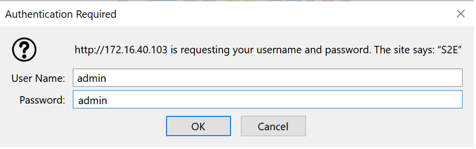
Default web UI username and password
admin
To reset the control network address use the USR IOT tool
The tool does allow you to search and reset the network settings
To configure the AES67 network address use the built in Audiolan web UI. Your PC needs to be connected to the AES67 network and have its addressing set in the same IP range.
By default the AES67 network interface is set to the static IP address (192.168.4.233)
To avoid an IP conflicts, connect one device after another and change each units IP to a different one
Avoid any special characters and spaces in the device name

The AES67 stream of each device needs to be configured to be received by the Dante/AES67 devices
Avoid any special characters and spaces in the stream name

Natively the audio routing can be done by using Audinate’s Dante Controller in case if its not auto configured by the DSP’s management software. In Dante Controller all your Dante and AES67 devices that are connected to the network will show up automatically.
The MCP4kR2 will be shown at the ‘‘Dante Transmitters’’ part, using its multicast address@hostname-HH-HH-HH where ‘‘HH-HH-HH’’ are the last three bytes of the devices MAC address.

In case of NGTC DSP hardware, the audio routing is done by using the Symetrix Symnet Composer. Please make sure all your Dante and AES67 devices that are connected to the network and are online. You might check this using Dante Controller.
Create a 8 channel network AES67 receive module:

This will connect the MCP4kR2 AES67 stream to the DSP while going online. There is no need to use the Dante Controller to do the connection.
The audio configurations can be set via the control protocol
Available speaker Setup:
Available post processing:
This section describes the communication protocol between the control system and the MCP4k
| Connection | TCP (NGTC-MCP4k is server), Port 20108 |
| Command Format | h07CommandParameter)hB3h0Dh0A or h07CommandhB3 h0D h0A |
All commands start with h07 which is hex 07, end with hB3h0Dh0A which is in hex B3, 0D and 0A
If a command has a parameter, the parameter is right after the command, with no whitespaces inbetween
Send only one command at the time and wait for reply before sending the next one
| Communication | Get Version |
|---|---|
| Request | h07GVERhB3h0Dh0A |
| Reply | h07RVER000hB3h0Dh0A |
| Communication | Get Version |
|---|---|
| Request | h07GVERhB3h0Dh0A |
| Reply | h07RVER000hB3h0Dh0A |
| Communication | Command | Parameter | Example |
|---|---|---|---|
| Request | h07SINPhB3h0Dh0A |
||
| 000: HDMI 1 | |||
| 001: HDMI 2 | |||
| 002: HDMI 3 | |||
| 003: HDMI 4 | |||
| 004: SPDIF | |||
| 005: Analog | |||
h07SINP002hB3h0Dh0A |
|||
| Reply |
| Communication | Command | Parameter | Example |
|---|---|---|---|
| Request | h07GINP000hB3h0Dh0A |
||
h07GINP000hB3h0Dh0A |
|||
| Reply | h07RINP002hB3h0Dh0A |
| Communication | Command | Parameter | Example |
|---|---|---|---|
| Request | h07SMODhB3h0Dh0A |
||
| 2.1: 2ch, full range | |||
| 3.1: 2ch, full range, LFE | |||
| 5.1: 5ch, full range, LFE | |||
| 7.1: 5ch, full range, LFE | |||
h07SMOD003hB3h0Dh0A |
|||
| Reply |
| Communication | Command | Parameter | Example |
|---|---|---|---|
| Request | h07GMODhB3h0Dh0A |
||
h07GMODhB3h0Dh0A |
|||
| Reply | h07RMOD003hB3h0Dh0A |
| Communication | Command | Parameter | Example |
|---|---|---|---|
| Request | h07SDSPhB3h0Dh0A |
||
| 0: None | |||
| 1: STEREO | |||
| 2: PROLOGIC II MUSIC | |||
| 3: PROLOGIC II MOVIE | |||
| 4: DTS NEO6 MUSIC | |||
| 4: DTS NEO6 MOVIE | |||
h07SDSP004hB3h0Dh0A |
|||
| Reply |
| Communication | Command | Parameter | Example |
|---|---|---|---|
| Request | h07GDSP000hB3h0Dh0A |
||
h07GDSP000hB3h0Dh0A |
|||
| Reply | h07RDSP004hB3h0Dh0A |
| Communication | Command | Parameter | Example |
|---|---|---|---|
| Request | h07GSFO000hB3h0Dh0A |
||
| 1: Idle | |||
| 2: PCM | |||
| 4: Bitstream compressed 1 | |||
| 8: Bitstream compressed 2 | |||
| 32: HD Audio | |||
h07GSFO000hB3h0Dh0A |
|||
| Reply | h07RSFO001hB3h0Dh0A |
| HDMI | |
| Type | HDMI 1.4/HDCP 1.0 |
| Matrix | 1 x 1 Input selector, no scaling |
| Digital Audio Input | |
| Type | TOSLINK |
| Format | PCM, LPCM, DD, DTS up to 6 channels. 24Bit/192kHz Audio |
| Digital Audio Output | |
| Type | 8 channels, full range |
| Format | Aes67 |
| Audio Performance | |
| Format | PCM, LPCM, DD, DTS |
| Freq. Response | 20Hz – 20kHz, +/- 1dB |
| Video Performance | |
| Format | Up to 4k, 3D, 48Bit deep color |
| AES67 Network with WebUI | |
| Physical Level | Standard Ethernet |
| Connector | Single RJ-45 |
| Cable Quality | CAT-5/6/7 |
| Transmission Speed | 100 Mbps Full Duplex |
| Control Network with WebUI | |
| Physical Level | Standard Ethernet |
| Connector | Single RJ-45 |
| Cable Quality | CAT-5/6/7 |
| Transmission Speed | 100 Mbps Full Duplex |
| General | |
| Power | POE, 10W max |
| Total heat dissipation | <50.00 BTU/hr |
| Operating temp | 0°C – 60°C |
| Dimensions | L: 250mm, W: 208mm, H:44mm |
| Compliance | CE, ROHS |
| Weight | 2kg |
| Channel | Assignment |
|---|---|
| 1 | Center Front |
| 2 | LFE |
| 3 | Left Rear |
| 4 | Right Rear |
| 5 | Left Front |
| 6 | Right Front |
| 7 | Left Surround |
| 8 | Right Surrounc |
The MCP4k is half rack width and one rack unit high. If positioned in the rack, it can be mounted the rack shelf that is available. A half rack filler panel is available as well.


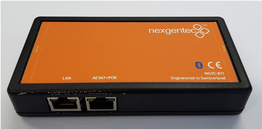
The NGTC-BTIR2 is a universal Bluetooth® AES67 enabled audio interface for the Genesis Technologies™ audio distribution solution.
It features an API for navigation, configuration and management.
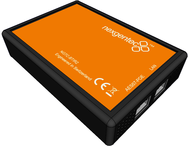
The NGTC-BTIR2 is a Bluetooth 5.0 to AES67 audio gateway that can be used in sink or source mode. It supports all current audio codes and it is compatible with all the different Bluetooth sources and sinks. It has 2x2 AES67 channels with an interface for audio processing by the NGTC digital signal processor.
It can be easily interfaced with 3rd party control systems via the API on the communication control network port.
It is powered by POE on the AES67 port. Its own web UI is used to configure the AES67 interface. The additional LAN port is only used for control and can be configured by web UI.
The NGTC-BTI Bluetooth interface is working in the 2.4Ghz band. It is essential to mount it as “free” are possible in the space to not reduce reception. Any metal shielding should be avoided!
The BTI should be mounted on a flat surface with it’s two mounting brackets

All connections to the NGTC-BTI should be made before power is applied
• Attach the LAN network port to the control network switch, using an UTP CAT-5 cable
• Attach the AES67 network port to the AES67/Dante POE network switch, using an UTP CAT-5 cable.
AES67 interoperability settings are required for every Dante device that should receive a AES67 stream
To enable your Dante devices to receive an AES67 stream, AES67 interoperability must be enabled. This is done by using Audinate’s Dante Controller, which can be obtained from the Audinate website or any other manufacturer specific software tool.
In Dante controller all your Dante devices that are connected to the network will show up automatically.
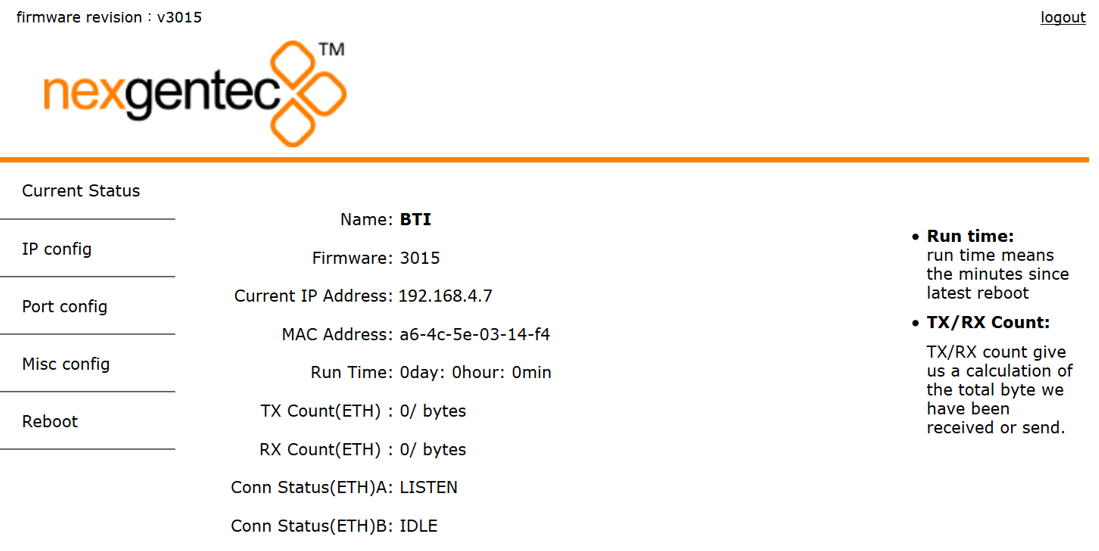
The setup of the control network of the BTI will be done via it’s Web UI. It is self-explaining
By default the interface is set to DHCP
Please make sure your computer network address is in the same network range to access the setup pages
Default web UI username and password
admin
Refer to the MAC address if multiple MCP’s are in the network to identify the right unit. The MAC address is also printed on each units bottom cover as QR Code.
To reset the control network address use the USR IOT tool
The tool does allow you to search and reset the network settings
To configure the AES67 download latest generation Audio Grid Controller Software. Your PC needs to be connected to the AES67 network and have its addressing set in the same IP range.
Start the software and go to the “Device Config” tab
The AES67 stream of each device needs to be configured to be received by the Dante/AES67 devices
Start the software and go to the “Device Config” tab


Natively the audio routing can be done by using Audinate’s Dante Controller in case if its not auto configured by the DSP’s management software. In Dante Controller all your Dante and AES67 devices that are connected to the network will show up automatically.
The BTI will be shown at the ‘‘Dante Transmitters’’ part, using its multicast address@hostname-HH-HH-HH where ‘‘HH-HH-HH’’ are the last three bytes of the devices MAC address.
This section describes the communication protocol between the control system and the BTI
The BTI Configurator does use the same protocol, see its debug window for more information
Please use >80ms between each command sent
| Connection | TCP (NGTC-BTI is server), Port 20108 |
| Command Format | AT+ Command {=Param1{, Param2{, Param3…}}}<CR><LF> |
| Reply Format | <CR><LF>+reply {=Param1{, Param2{, Param3…}}} <CR><LF> |
<CR> stands for “carriage return”, corresponding hex is 0x0D
<LF> stands for “line feed”, corresponding hex is 0x0A
Command Format Details
All commands start with “AT”, end with <CR><LF>
If a command has a parameter, the parameter is behind the “=”
If a command has multiple parameters, the parameters must be separated by “,”
Reply Format Details
All replies start with <CR><LF> and end with <CR><LF>
If a reply has a parameter, the parameter is behind the “=”
If a reply has multiple parameters, the parameters must be separated by “,”
The interface will always report the execution result using “OK” for success or “ERROR” for failure
| Communication | Command | Parameter | Example |
|---|---|---|---|
| Request | AT+NAME<CR><LF> |
||
AT+NAME<CR><LF> |
|||
| Reply #1 | <CR><LF>+NAME=NGTC-BTI<CR><LF> |
||
| Reply #2 | <CR><LF>OK<CR><LF> |
| Communication | Command | Parameter | Example |
|---|---|---|---|
| Request | AT+NAME=Parameter<CR><LF> |
||
| NGTC-BTI | |||
AT+NAME=NGTC-BTI<CR><LF> |
|||
| Reply | <CR><LF>OK<CR><LF> |
| Communication | Command | Parameter | Example |
|---|---|---|---|
| Request | AT+VER<CR><LF> |
||
AT+VER<CR><LF> |
|||
| Reply #1 | <CR><LF>>+VER=20171125,NGTC-BTI<CR><LF> |
||
| Reply #2 | <CR><LF>OK<CR><LF> |
| Communication | Command | Parameter | Example |
|---|---|---|---|
| Request | AT+ADDR<CR><LF> |
||
AT+ADDR<CR><LF> |
|||
| Reply #1 | <CR><LF>>+ADDR=DC0D30123456<CR><LF> |
||
| Reply #2 | <CR><LF>OK<CR><LF> |
| Communication | Command | Parameter | Example |
|---|---|---|---|
| Request | AT+NAME<CR><LF> |
||
AT+NAME<CR><LF> |
|||
| Reply #1 | <CR><LF>+NAME=NGTC-BTI<CR><LF> |
||
| Reply #2 | <CR><LF>OK<CR><LF> |
| Communication | Command | Parameter | Example |
|---|---|---|---|
| Request | AT+NAME=Parameter<CR><LF> |
||
| NGTC-BTI | |||
AT+NAME=NGTC-BTI<CR><LF> |
|||
| Reply | <CR><LF>OK<CR><LF> |
| Communication | Command | Parameter | Example |
|---|---|---|---|
| Request | AT+DSCA<CR><LF> |
||
AT+DSCA<CR><LF> |
|||
| Reply | <CR><LF>OK<CR><LF> |
| Communication | Command | Parameter | Example |
|---|---|---|---|
| Request | AT+REBOOT<CR><LF> |
||
AT+REBOOT<CR><LF> |
|||
| Reply | <CR><LF>OK<CR><LF> |
| Communication | Command | Parameter | Example |
|---|---|---|---|
| Request | AT+BTEN=Parameter<CR><LF> |
||
| 0: Undiscoverable | |||
| 1: operational | |||
AT+BTEN=1<CR><LF> |
|||
| Reply | <CR><LF>OK<CR><LF> |
| Communication | Command | Parameter | Example |
|---|---|---|---|
| Request | AT+BTEN<CR><LF> |
||
AT+BTEN<CR><LF> |
|||
| Reply #1 | <CR><LF>+BTEN=1<CR><LF> |
||
| Reply #2 | <CR><LF>OK<CR><LF> |
Status parameter will be reported in bit representation
| Communication | Command | Parameter | Example |
|---|---|---|---|
| Request | AT+DEVSTAT<CR><LF> |
||
| BIT[0]: PWR OFF; 1: PWR ON | |||
| BIT[1]: Non Discoverable; 1: Discoverable | |||
| BIT[2]: Non Advertising; 1: Advertising | |||
| BIT[3]: Non Scanning; 1: Scanning | |||
AT+DEVSTAT<CR><LF> |
|||
| Reply #1 | <CR><LF>+DEVSTAT=9<CR><LF> |
||
| Reply #2 | <CR><LF>OK<CR><LF> |
This command needs a reboot to activate
| Communication | Command | Parameter | Example |
|---|---|---|---|
| Request | AT+AUTOCONN=Parameter<CR><LF> |
||
| 0: Off | |||
| 1: 15 Attempts | |||
AT+AUTOCONN=0<CR><LF> |
|||
| Reply | <CR><LF>OK<CR><LF> |
| Communication | Command | Parameter | Example |
|---|---|---|---|
| Request | AT+AUTOCONN<CR><LF> |
||
AT+AUTOCONN<CR><LF> |
|||
| Reply #1 | <CR><LF>+AUTOCONN=1<CR><LF> |
||
| Reply #2 | <CR><LF>OK<CR><LF> |
BTI module needs to be power cycled afterwards
| Communication | Command | Parameter | Example |
|---|---|---|---|
| Request | AT+RESTORE<CR><LF> |
||
AT+RESTORE<CR><LF> |
|||
| Reply | <CR><LF>OK<CR><LF> |
Please watch the volume carefully
There is no real standard for the source volume.
If you all the way to 15, you may overload the interface and it will result in distortion
| Communication | Command | Parameter | Example |
|---|---|---|---|
| Request | AT+SPKVOL=Parameter<CR><LF> |
||
| +: UP | |||
| -: DOWN | |||
AT+SPKVOL=+<CR><LF> |
|||
| Reply | <CR><LF>OK<CR><LF> |
| Communication | Command | Parameter | Example |
|---|---|---|---|
| Request | AT+SPKVOL<CR><LF> |
||
AT+SPKVOL<CR><LF> |
|||
| Reply #1 | <CR><LF>+SPKVOL=10<CR><LF> |
||
| Reply #2 | <CR><LF>OK<CR><LF> |
BTI module will reboot and all device profiles will be deleted
| Communication | Command | Parameter | Example |
|---|---|---|---|
| Request | AT+A2DPROLE=Parameter<CR><LF> |
||
| 0: Sink | |||
| 1: Source | |||
AT+A2DPROLE=0<CR><LF> |
|||
| Reply | <CR><LF>OK<CR><LF> |
| Communication | Command | Parameter | Example |
|---|---|---|---|
| Request | AT+A2DPROLE<CR><LF> |
||
AT+A2DPROLE<CR><LF> |
|||
| Reply #1 | <CR><LF>+A2DPROLE=1<CR><LF> |
||
| Reply #2 | <CR><LF>OK<CR><LF> |
To use the commands below the BTI needs to be switched to sink mode first
| Communication | Command | Parameter | Example |
|---|---|---|---|
| Request | AT+PAIR=Parameter<CR><LF> |
||
| 0: Off | |||
| 1: On | |||
AT+PAIR=1<CR><LF> |
|||
| Reply | <CR><LF>OK<CR><LF> |
| Communication | Command | Parameter | Example |
|---|---|---|---|
| Request | AT+PAIR<CR><LF> |
||
AT+PAIR<CR><LF> |
|||
| Reply #1 | <CR><LF>+PAIR=1<CR><LF> |
||
| Reply #2 | <CR><LF>OK<CR><LF> |
| Communication | Command | Parameter | Example |
|---|---|---|---|
| Request | AT+SSP=Parameter<CR><LF> |
||
| 0: Off | |||
| 1: On | |||
AT+SSP=1<CR><LF> |
|||
| Reply | <CR><LF>OK<CR><LF> |
| Communication | Command | Parameter | Example |
|---|---|---|---|
| Request | AT+SSP<CR><LF> |
||
AT+SSP<CR><LF> |
|||
| Reply #1 | <CR><LF>+SSP=0<CR><LF> |
||
| Reply #2 | <CR><LF>OK<CR><LF> |
| Communication | Command | Parameter | Example |
|---|---|---|---|
| Request | AT+PIN=Parameter<CR><LF> |
||
| 4-15 ASCII numbers | |||
AT+PIN=1234<CR><LF> |
|||
| Reply | <CR><LF>OK<CR><LF> |
| Communication | Command | Parameter | Example |
|---|---|---|---|
| Request | AT+PIN<CR><LF> |
||
AT+PIN<CR><LF> |
|||
| Reply #1 | <CR><LF>+PIN=1234<CR><LF> |
||
| Reply #2 | <CR><LF>OK<CR><LF> |
If the device (headphone/speaker) is deleted in the BTI it needs to be reconnected to work
| Communication | Command | Parameter | Example |
|---|---|---|---|
| Request | AT+PLIST=Parameter<CR><LF> |
||
| 0: Clear list | |||
| x: Clear index (x) | |||
AT+PLIST=E<CR><LF> |
|||
| Reply | <CR><LF>OK<CR><LF> |
| Communication | Command | Parameter | Example |
|---|---|---|---|
| Request | AT+PLIST<CR><LF> |
||
AT+PLIST<CR><LF> |
|||
| Reply #1 | <CR><LF>+PLIST=1,123456ABCDEF <CR><LF><CR><LF>+PLIST=1,ABCDEF123456 <CR><LF><CR><LF>+PLIST=E <CR><LF> |
||
| Reply #2 | <CR><LF>OK<CR><LF> |
| Communication | Command | Parameter | Example |
|---|---|---|---|
| Request | AT+A2DPCONN=Parameter<CR><LF> |
||
| No parameter: To last device | |||
| MAC: Mac of target device (12 Bytes ASCII) | |||
AT+A2DPCONN=123456ABCEDF<CR><LF> |
|||
| Reply #1 | <CR><LF>+A2DPCONN=123456ABCEDF<CR><LF> |
||
| Reply #2 | <CR><LF>OK<CR><LF> |
| Communication | Command | Parameter | Example |
|---|---|---|---|
| Request | AT+A2DPDISC<CR><LF> |
||
AT+A2DPDISC<CR><LF> |
|||
| Reply | <CR><LF>OK<CR><LF> |
| Communication | Command | Parameter | Example |
|---|---|---|---|
| Request | AT+A2DPSTAT<CR><LF> |
||
AT+A2DPSTAT<CR><LF> |
|||
| Reply #1 | <CR><LF>+A2DPSTAT=4<CR><LF> |
||
| 0: Unsupported | |||
| 1: Standby | |||
| 2: Connecting | |||
| 3: Connected | |||
| 4: Streaming | |||
| Reply #2 | <CR><LF>OK<CR><LF> |
Event at device connection only, cannot be requested by control system
| Communication | Command | Parameter | Example |
|---|---|---|---|
| Reply #1 | <CR><LF>+A2DPDEV=123456ABCDEF <CR><LF> |
||
| Reply #2 | <CR><LF>OK<CR><LF> |
| Communication | Command | Parameter | Example |
|---|---|---|---|
| Request | AT+A2DPDEC<CR><LF> |
||
AT+A2DPDEC<CR><LF> |
|||
| Reply #1 | <CR><LF>+A2DPDEC=1<CR><LF> |
||
| 0: Invalid | |||
| 1: SBC | |||
| 2: MP3 | |||
| 3: AAC | |||
| 4: FASTSTREAM | |||
| 5: APTX | |||
| 6: APTX-Sprint | |||
| 7: APTX-HD | |||
| 8: APTX-LL | |||
| Reply #2 | <CR><LF>OK<CR><LF> |
This command needs a reboot to activate
| Communication | Command | Parameter | Example |
|---|---|---|---|
| Request | AT+AVRCPCFG<CR><LF> |
||
| BIT[0]: Auto get rack ID3 information (title, artist, album) on track changed (default 1) | |||
| BIT[1-3]: Auto get track state (play progress) if value >0 (default 5sec) | |||
AT+AVRCPCFG=11<CR><LF> |
|||
| Reply | <CR><LF>OK<CR><LF> |
| Communication | Command | Parameter | Example |
|---|---|---|---|
| Request | AT+AVRCPSTAT<CR><LF> |
||
AT+AVRCPSTAT<CR><LF> |
|||
| Reply #1 | <CR><LF>+AVRCPSTAT=4<CR><LF> |
||
| 0: Unsupported | |||
| 1: Standby | |||
| 2: Connecting | |||
| 3: Connected | |||
| Reply #2 | <CR><LF>OK<CR><LF> |
Event at device connection only, cannot be requested by control system
| Communication | Command | Parameter | Example |
|---|---|---|---|
| Param1: (0-4) Media Player State – please see PLAYSTAT parameters | |||
| Param2:(Decimal ASCII), Elapsed time of current track in ms | |||
| Param3:(Decimal ASCII), Total time of track in ms | |||
| Reply #1 | <CR><LF>+TRACKSTAT=1,142000,248000 <CR><LF> |
Event at device connection only, cannot be requested by control system
| Communication | Command | Parameter | Example |
|---|---|---|---|
| Param1: Title | |||
| Param2: Artist | |||
| Param3: Album | |||
| Reply #1 | <CR><LF>+TRACKINFO=Creep<FF>Radiohead<FF>Pablo Honey <CR><LF> |
Event at device connection only, cannot be requested by control system
| Communication | Command | Parameter | Example |
|---|---|---|---|
| 0: Stopped | |||
| 1: Playing | |||
| 2: Paused | |||
| 3: Fast Forward | |||
| 4: Fast Rewind | |||
| Reply #1 | <CR><LF>+PLAYSTAT=1<CR><LF> |
| Communication | Command | Parameter | Example |
|---|---|---|---|
| Request | AT+PLAYPAUSE<CR><LF> |
||
AT+PLAYPAUSE<CR><LF> |
|||
| Reply | <CR><LF>OK<CR><LF> |
| Communication | Command | Parameter | Example |
|---|---|---|---|
| Request | AT+PLAY<CR><LF> |
||
AT+PLAY<CR><LF> |
|||
| Reply | <CR><LF>OK<CR><LF> |
| Communication | Command | Parameter | Example |
|---|---|---|---|
| Request | AT+PAUSE<CR><LF> |
||
AT+PAUSE<CR><LF> |
|||
| Reply | <CR><LF>OK<CR><LF> |
| Communication | Command | Parameter | Example |
|---|---|---|---|
| Request | AT+STOP<CR><LF> |
||
AT+STOP<CR><LF> |
|||
| Reply | <CR><LF>OK<CR><LF> |
| Communication | Command | Parameter | Example |
|---|---|---|---|
| Request | AT+FORWARD<CR><LF> |
||
AT+FORWARD<CR><LF> |
|||
| Reply | <CR><LF>OK<CR><LF> |
| Communication | Command | Parameter | Example |
|---|---|---|---|
| Request | AT+BACKWARD<CR><LF> |
||
AT+BACKWARD<CR><LF> |
|||
| Reply | <CR><LF>OK<CR><LF> |
To use the commands below the BTI needs to be switched to source mode first
| Communication | Command | Parameter | Example |
|---|---|---|---|
| Request | AT+INQCFG=Parameter<CR><LF> |
||
| 0: Off | |||
| 1: On | |||
AT+INQCFG=1<CR><LF> |
|||
| Reply | <CR><LF>OK<CR><LF> |
| Communication | Command | Parameter | Example |
|---|---|---|---|
| Request | AT+INQCFG<CR><LF> |
||
AT+INQCFG<CR><LF> |
|||
| Reply #1 | <CR><LF>+INQCFG=10<CR><LF> |
||
| Reply #2 | <CR><LF>OK<CR><LF> |
If the device (headphone/speaker) is deleted in the BTI it needs to be reconnected to work
| Communication | Command | Parameter | Example |
|---|---|---|---|
| Request | AT+PLIST=Parameter<CR><LF> |
||
| 0: Clear list | |||
| x: Clear index (x) | |||
AT+PLIST=E<CR><LF> |
|||
| Reply | <CR><LF>OK<CR><LF> |
| Communication | Command | Parameter | Example |
|---|---|---|---|
| Request | AT+PLIST<CR><LF> |
||
AT+PLIST<CR><LF> |
|||
| Reply #1 | <CR><LF>+PLIST=1,123456ABCDEF <CR><LF><CR><LF>+PLIST=1,ABCDEF123456 <CR><LF><CR><LF>+PLIST=E <CR><LF> |
||
| Reply #2 | <CR><LF>OK<CR><LF> |
| Communication | Command | Parameter | Example |
|---|---|---|---|
| Request | AT+A2DPCONN=Parameter<CR><LF> |
||
| No parameter: To last device | |||
| MAC: Mac of target device (12 Bytes ASCII) | |||
AT+A2DPCONN=123456ABCEDF<CR><LF> |
|||
| Reply #1 | <CR><LF>+A2DPCONN=123456ABCEDF<CR><LF> |
||
| Reply #2 | <CR><LF>OK<CR><LF> |
| Communication | Command | Parameter | Example |
|---|---|---|---|
| Request | AT+A2DPDISC<CR><LF> |
||
AT+A2DPDISC<CR><LF> |
|||
| Reply | <CR><LF>OK<CR><LF> |
| Communication | Command | Parameter | Example |
|---|---|---|---|
| Request | AT+A2DPSTAT<CR><LF> |
||
AT+A2DPSTAT<CR><LF> |
|||
| Reply #1 | <CR><LF>+A2DPSTAT=4<CR><LF> |
||
| 0: Unsupported | |||
| 1: Standby | |||
| 2: Connecting | |||
| 3: Connected | |||
| 4: Streaming | |||
| Reply #2 | <CR><LF>OK<CR><LF> |
Event at device connection only, cannot be requested by control system
| Communication | Command | Parameter | Example |
|---|---|---|---|
| Reply #1 | <CR><LF>+A2DPDEV=123456ABCDEF <CR><LF> |
||
| Reply #2 | <CR><LF>OK<CR><LF> |
| Communication | Command | Parameter | Example |
|---|---|---|---|
| Request | AT+A2DPDEC<CR><LF> |
||
AT+A2DPDEC<CR><LF> |
|||
| Reply #1 | <CR><LF>+A2DPDEC=1<CR><LF> |
||
| 1: SBC | |||
| 5: APTX | |||
| 6: APTX-LL | |||
| Reply #2 | <CR><LF>OK<CR><LF> |
| OS Support | |
| OS | iOS, PC, MAC and Android |
| Bluetooth | |
| Standards | V5 down to V1.1, Class 1.5 |
| Band | 2.402 – 2.480 GHz |
| Audio Format | All (SBC,aptx HD,LL) |
| AES67 Network with WebUI | |
| Physical Level | Standard Ethernet |
| Connector | Single RJ-45 |
| Cable Quality | CAT-5/6/7 |
| Transmission Speed | 100 Mbps Full Duplex |
| Control Network with WebUI | |
| Physical Level | Standard Ethernet |
| Connector | Single RJ-45 |
| Cable Quality | CAT-5/6/7 |
| Transmission Speed | 100 Mbps Full Duplex |
| General | |
| Power | POE, 3W max |
| Total heat dissipation | max 10.00 BTU/hr |
| Operating temp | 5°C – 30°C |
| Dimensions | L: 110mm, W: 74mm, H:25mm |
| Compliance | CE, ROHS |
| Channel | Assignment |
|---|---|
| 1 | Left Channel |
| 2 | Right Channel |
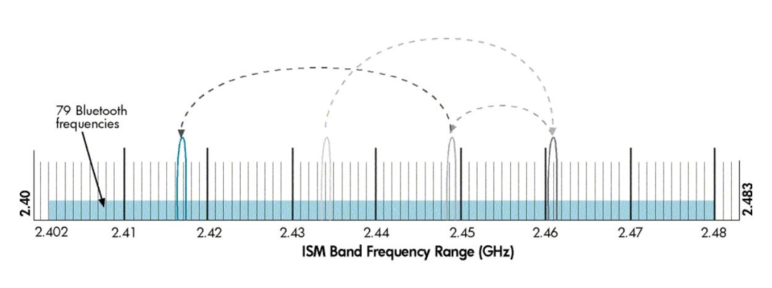
The simplest explanation for how Bluetooth works is that data/audio is continuously transferred from a paired Bluetooth transmitter to a paired receiver. Pairing is just the bonding procedure between devices so that you don’t have to enter access or security information, like passwords or passkeys, each time the devices need to establish a connection. Bluetooth operates in the frequency range of (2.402 -2.480GHz). Once a secure connection is established between a transmitter and receiver, data is split into small packets, which are then transferred at alternating frequencies. The type of Bluetooth and profiles may vary, but the core architecture remains the same. To avoid interference with other devices that may also use the ISM (industrial, science, and medical) bandwidth of 2.4Ghz, Bluetooth devices randomly hop between frequencies 1600 times per second until all the packets are transferred.
The NGTC-BTI supports Bluetooth 5.x, the most recent iteration of Bluetooth. It has twice the bandwidth of V4.x. The NGTC-BTI supports only audio related transmission, no data communication or phone/handsfree functionality.
Stereo audio transmission. This is the most important profile for Bluetooth as mono audio is not suited for listening to music.
Adds control for media playback such as skipping tracks, play/pause, and meta data.
Codecs are encoding and decoding algorithms that compress audio into manageable data packets for faster or wireless transmission. The efficiency of the codec will determine the quality and rate at which the audio data is sent. SBC is the default sub-band coding for most Bluetooth devices. However, since this codec has a relatively high latency and may be a bit lossy, companies have developed their own encoding algorithms.
The mandatory and default codec for all stereo Bluetooth headphones with the Advanced Audio Distribution Profile (A2DP). It is capable of bit rates up to 328 kbps with a sampling rate of 44.1kHz. It provides fairly good audio quality without requiring a lot of processing power to encode or decode. However, the audio quality can be a bit inconsistent at times. This is especially noticeable with a cheap Bluetooth transmitter.
Similar to SBC, but with better sound quality. This codec is mostly popular with Apple’s iTunes platform and some other non-wireless applications. However, it’s not very common, especially for headphones.
It’s ideal for demanding audio applications since it encodes audio more efficiently and at a slightly higher rate than SBC. There are also two additional variations, aptX Low Latency and aptX HD, that either drastically reduces the latency of the connection or significantly improves its audio quality. However, it’s a bit limiting, as both the Bluetooth transmitter and receiver must have aptX or its variations for the codec to work.
Codecs have a bigger impact on latency than on sound quality for most listeners. The default SBC connection typically has more than 100ms of latency, which is noticeable when listening to music but may be severe enough to ruin your movie experience. To fix some of the sync issues caused by latency, CSR developed the aptX and subsequently the aptX Low Latency codec. Regular aptX does somewhat improve latency due to its more efficient encoding algorithm than SBC. However, aptX-LL has the most noticeable impact on latency.
| Codec | Latency |
|---|---|
| SBC | 173ms |
| aptX | 166ms |
| aptx LL | 34ms |
Codecs are the algorithms that compress data for easier and faster transmission. Better encoding and decoding algorithms mean less lossy transmission which can help with audio quality. We have noticed that codecs have a bigger impact on latency than on audio quality. The subtle changes in audio quality due to a codec like aptX are negligible when compared to the reduced latency aptX Low Latency connection. However, since both Bluetooth devices (source/sink) have to support the codec for it to work, you will most often rely on the default sub-band coding (SBC), as there are not many Bluetooth devices that support aptX and even less for aptX-LL.
Welcome to the Firmware section!
If you are not redirected automatically, click here.
The latest generation of BTIR2 features an AES67 daughter board that fully supports AES67, ensuring compatibility with Dante™. Additionally, these devices have mDNS discovery enabled, allowing them to be detected in the Dante Controller, similar to a Dante product.
However, starting with Dante Controller V12, a pop-up message may appear indicating that unlicensed Dante™ products are being used. To address this, the new firmware will disable Dante™ discovery, and all R2 units will be recognized as AES67 devices.

After the reboot, click “Refresh” to update the device list. If the devices appear as expected, you can proceed with the update process.

After the reboot, you need to set the multicast address for AES67 to work. Use the Audio Grid Controller to do this.
Refer to the following instructions to configure it with the AudioGrid controller
The NGTC-BTI is a universal Bluetooth® AES67 enabled audio interface for the Genesis Technologies™ audio distribution solution.
It features an API for navigation, configuration and management.
The NGTC-BTI is a Bluetooth 5.0 to AES67 audio gateway that can be used in sink or source mode. It supports all current audio codes and it is compatible with all the different Bluetooth sources and sinks. It has 2x2 AES67 channels with an interface for audio processing by the NGTC digital signal processor.
It can be easily interfaced with 3rd party control systems via the API on the communication control network port.
It is powered by POE on the AES67 port. Its own web UI is used to configure the AES67 interface. The additional LAN port is only used for control and can be configured by web UI.
The NGTC-BTI Bluetooth interface is working in the 2.4Ghz band. It is essential to mount it as “free” are possible in the space to not reduce reception. Any metal shielding should be avoided!
The BTI should be mounted on a flat surface with it’s two mounting brackets

All connections to the NGTC-BTI should be made before power is applied
• Attach the LAN network port to the control network switch, using an UTP CAT-5 cable
• Attach the AES67 network port to the AES67/Dante POE network switch, using an UTP CAT-5 cable.
AES67 interoperability settings are required for every Dante device that should receive a AES67 stream
To enable your Dante devices to receive an AES67 stream, AES67 interoperability must be enabled. This is done by using Audinate’s Dante Controller, which can be obtained from the Audinate website or any other manufacturer specific software tool.
In Dante controller all your Dante devices that are connected to the network will show up automatically.

The setup of the control network of the BTI will be done via it’s Web UI. It is self-explaining
By default the interface is set to 192.168.4.7
Please make sure your computer network address is in the same network range to access the setup pages
Default web UI username and passwordadmin


Refer to the MAC address if multiple MCP’s are in the network to identify the right unit. The MAC address is also printed on each units bottom cover as QR Code.
To reset the control network address use the USR IOT tool
The tool does allow you to search and reset the network settings
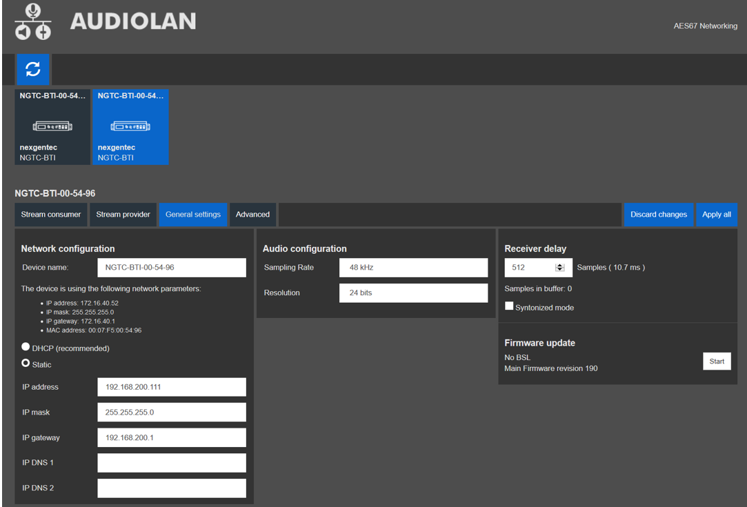
To configure the AES67 network address use the built in Audiolan web UI. Your PC needs to be connected to the AES67 network and have its addressing set in the same IP range.
By default the AES67 network interface is set to the static IP address (192.168.4.233)
Avoid any special characters and spaces in the device name
The AES67 stream of each device needs to be configured to be received by the Dante/AES67 devices
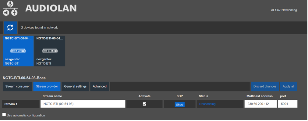
The receiving AES67 part of the NGTC-BTI device needs to be configured in the Audiolan Web UI.
Natively the audio routing can be done by using Audinate’s Dante Controller in case if its not auto configured by the DSP’s management software. In Dante Controller all your Dante and AES67 devices that are connected to the network will show up automatically.
The BTI will be shown at the ‘‘Dante Transmitters’’ part, using its multicast address@hostname-HH-HH-HH where ‘‘HH-HH-HH’’ are the last three bytes of the devices MAC address.

This section describes the communication protocol between the control system and the BTI
The BTI Configurator does use the same protocol, see its debug window for more information
Please use >80ms between each command sent
| Connection | TCP (NGTC-BTI is server), Port 20108 |
| Command Format | AT+ Command {=Param1{, Param2{, Param3…}}}<CR><LF> |
| Reply Format | <CR><LF>+reply {=Param1{, Param2{, Param3…}}} <CR><LF> |
<CR> stands for “carriage return”, corresponding hex is 0x0D
<LF> stands for “line feed”, corresponding hex is 0x0A
Command Format Details
All commands start with “AT”, end with <CR><LF>
If a command has a parameter, the parameter is behind the “=”
If a command has multiple parameters, the parameters must be separated by “,”
Reply Format Details
All replies start with <CR><LF> and end with <CR><LF>
If a reply has a parameter, the parameter is behind the “=”
If a reply has multiple parameters, the parameters must be separated by “,”
The interface will always report the execution result using “OK” for success or “ERROR” for failure
| Communication | Command | Parameter | Example |
|---|---|---|---|
| Request | AT+NAME<CR><LF> |
||
AT+NAME<CR><LF> |
|||
| Reply #1 | <CR><LF>+NAME=NGTC-BTI<CR><LF> |
||
| Reply #2 | <CR><LF>OK<CR><LF> |
| Communication | Command | Parameter | Example |
|---|---|---|---|
| Request | AT+NAME=Parameter<CR><LF> |
||
| NGTC-BTI | |||
AT+NAME=NGTC-BTI<CR><LF> |
|||
| Reply | <CR><LF>OK<CR><LF> |
| Communication | Command | Parameter | Example |
|---|---|---|---|
| Request | AT+VER<CR><LF> |
||
AT+VER<CR><LF> |
|||
| Reply #1 | <CR><LF>>+VER=20171125,NGTC-BTI<CR><LF> |
||
| Reply #2 | <CR><LF>OK<CR><LF> |
| Communication | Command | Parameter | Example |
|---|---|---|---|
| Request | AT+ADDR<CR><LF> |
||
AT+ADDR<CR><LF> |
|||
| Reply #1 | <CR><LF>>+ADDR=DC0D30123456<CR><LF> |
||
| Reply #2 | <CR><LF>OK<CR><LF> |
| Communication | Command | Parameter | Example |
|---|---|---|---|
| Request | AT+NAME<CR><LF> |
||
AT+NAME<CR><LF> |
|||
| Reply #1 | <CR><LF>+NAME=NGTC-BTI<CR><LF> |
||
| Reply #2 | <CR><LF>OK<CR><LF> |
| Communication | Command | Parameter | Example |
|---|---|---|---|
| Request | AT+NAME=Parameter<CR><LF> |
||
| NGTC-BTI | |||
AT+NAME=NGTC-BTI<CR><LF> |
|||
| Reply | <CR><LF>OK<CR><LF> |
| Communication | Command | Parameter | Example |
|---|---|---|---|
| Request | AT+DSCA<CR><LF> |
||
AT+DSCA<CR><LF> |
|||
| Reply | <CR><LF>OK<CR><LF> |
| Communication | Command | Parameter | Example |
|---|---|---|---|
| Request | AT+REBOOT<CR><LF> |
||
AT+REBOOT<CR><LF> |
|||
| Reply | <CR><LF>OK<CR><LF> |
| Communication | Command | Parameter | Example |
|---|---|---|---|
| Request | AT+BTEN=Parameter<CR><LF> |
||
| 0: Undiscoverable | |||
| 1: operational | |||
AT+BTEN=1<CR><LF> |
|||
| Reply | <CR><LF>OK<CR><LF> |
| Communication | Command | Parameter | Example |
|---|---|---|---|
| Request | AT+BTEN<CR><LF> |
||
AT+BTEN<CR><LF> |
|||
| Reply #1 | <CR><LF>+BTEN=1<CR><LF> |
||
| Reply #2 | <CR><LF>OK<CR><LF> |
Status parameter will be reported in bit representation
| Communication | Command | Parameter | Example |
|---|---|---|---|
| Request | AT+DEVSTAT<CR><LF> |
||
| BIT[0]: PWR OFF; 1: PWR ON | |||
| BIT[1]: Non Discoverable; 1: Discoverable | |||
| BIT[2]: Non Advertising; 1: Advertising | |||
| BIT[3]: Non Scanning; 1: Scanning | |||
AT+DEVSTAT<CR><LF> |
|||
| Reply #1 | <CR><LF>+DEVSTAT=9<CR><LF> |
||
| Reply #2 | <CR><LF>OK<CR><LF> |
This command needs a reboot to activate
| Communication | Command | Parameter | Example |
|---|---|---|---|
| Request | AT+AUTOCONN=Parameter<CR><LF> |
||
| 0: Off | |||
| 1: 15 Attempts | |||
AT+AUTOCONN=0<CR><LF> |
|||
| Reply | <CR><LF>OK<CR><LF> |
| Communication | Command | Parameter | Example |
|---|---|---|---|
| Request | AT+AUTOCONN<CR><LF> |
||
AT+AUTOCONN<CR><LF> |
|||
| Reply #1 | <CR><LF>+AUTOCONN=1<CR><LF> |
||
| Reply #2 | <CR><LF>OK<CR><LF> |
BTI module needs to be power cycled afterwards
| Communication | Command | Parameter | Example |
|---|---|---|---|
| Request | AT+RESTORE<CR><LF> |
||
AT+RESTORE<CR><LF> |
|||
| Reply | <CR><LF>OK<CR><LF> |
Please watch the volume carefully
There is no real standard for the source volume.
If you all the way to 15, you may overload the interface and it will result in distortion
| Communication | Command | Parameter | Example |
|---|---|---|---|
| Request | AT+SPKVOL=Parameter<CR><LF> |
||
| +: UP | |||
| -: DOWN | |||
AT+SPKVOL=+<CR><LF> |
|||
| Reply | <CR><LF>OK<CR><LF> |
| Communication | Command | Parameter | Example |
|---|---|---|---|
| Request | AT+SPKVOL<CR><LF> |
||
AT+SPKVOL<CR><LF> |
|||
| Reply #1 | <CR><LF>+SPKVOL=10<CR><LF> |
||
| Reply #2 | <CR><LF>OK<CR><LF> |
BTI module will reboot and all device profiles will be deleted
| Communication | Command | Parameter | Example |
|---|---|---|---|
| Request | AT+A2DPROLE=Parameter<CR><LF> |
||
| 0: Sink | |||
| 1: Source | |||
AT+A2DPROLE=0<CR><LF> |
|||
| Reply | <CR><LF>OK<CR><LF> |
| Communication | Command | Parameter | Example |
|---|---|---|---|
| Request | AT+A2DPROLE<CR><LF> |
||
AT+A2DPROLE<CR><LF> |
|||
| Reply #1 | <CR><LF>+A2DPROLE=1<CR><LF> |
||
| Reply #2 | <CR><LF>OK<CR><LF> |
To use the commands below the BTI needs to be switched to sink mode first
| Communication | Command | Parameter | Example |
|---|---|---|---|
| Request | AT+PAIR=Parameter<CR><LF> |
||
| 0: Off | |||
| 1: On | |||
AT+PAIR=1<CR><LF> |
|||
| Reply | <CR><LF>OK<CR><LF> |
| Communication | Command | Parameter | Example |
|---|---|---|---|
| Request | AT+PAIR<CR><LF> |
||
AT+PAIR<CR><LF> |
|||
| Reply #1 | <CR><LF>+PAIR=1<CR><LF> |
||
| Reply #2 | <CR><LF>OK<CR><LF> |
| Communication | Command | Parameter | Example |
|---|---|---|---|
| Request | AT+SSP=Parameter<CR><LF> |
||
| 0: Off | |||
| 1: On | |||
AT+SSP=1<CR><LF> |
|||
| Reply | <CR><LF>OK<CR><LF> |
| Communication | Command | Parameter | Example |
|---|---|---|---|
| Request | AT+SSP<CR><LF> |
||
AT+SSP<CR><LF> |
|||
| Reply #1 | <CR><LF>+SSP=0<CR><LF> |
||
| Reply #2 | <CR><LF>OK<CR><LF> |
| Communication | Command | Parameter | Example |
|---|---|---|---|
| Request | AT+PIN=Parameter<CR><LF> |
||
| 4-15 ASCII numbers | |||
AT+PIN=1234<CR><LF> |
|||
| Reply | <CR><LF>OK<CR><LF> |
| Communication | Command | Parameter | Example |
|---|---|---|---|
| Request | AT+PIN<CR><LF> |
||
AT+PIN<CR><LF> |
|||
| Reply #1 | <CR><LF>+PIN=1234<CR><LF> |
||
| Reply #2 | <CR><LF>OK<CR><LF> |
If the device (headphone/speaker) is deleted in the BTI it needs to be reconnected to work
| Communication | Command | Parameter | Example |
|---|---|---|---|
| Request | AT+PLIST=Parameter<CR><LF> |
||
| 0: Clear list | |||
| x: Clear index (x) | |||
AT+PLIST=E<CR><LF> |
|||
| Reply | <CR><LF>OK<CR><LF> |
| Communication | Command | Parameter | Example |
|---|---|---|---|
| Request | AT+PLIST<CR><LF> |
||
AT+PLIST<CR><LF> |
|||
| Reply #1 | <CR><LF>+PLIST=1,123456ABCDEF <CR><LF><CR><LF>+PLIST=1,ABCDEF123456 <CR><LF><CR><LF>+PLIST=E <CR><LF> |
||
| Reply #2 | <CR><LF>OK<CR><LF> |
| Communication | Command | Parameter | Example |
|---|---|---|---|
| Request | AT+A2DPCONN=Parameter<CR><LF> |
||
| No parameter: To last device | |||
| MAC: Mac of target device (12 Bytes ASCII) | |||
AT+A2DPCONN=123456ABCEDF<CR><LF> |
|||
| Reply #1 | <CR><LF>+A2DPCONN=123456ABCEDF<CR><LF> |
||
| Reply #2 | <CR><LF>OK<CR><LF> |
| Communication | Command | Parameter | Example |
|---|---|---|---|
| Request | AT+A2DPDISC<CR><LF> |
||
AT+A2DPDISC<CR><LF> |
|||
| Reply | <CR><LF>OK<CR><LF> |
| Communication | Command | Parameter | Example |
|---|---|---|---|
| Request | AT+A2DPSTAT<CR><LF> |
||
AT+A2DPSTAT<CR><LF> |
|||
| Reply #1 | <CR><LF>+A2DPSTAT=4<CR><LF> |
||
| 0: Unsupported | |||
| 1: Standby | |||
| 2: Connecting | |||
| 3: Connected | |||
| 4: Streaming | |||
| Reply #2 | <CR><LF>OK<CR><LF> |
Event at device connection only, cannot be requested by control system
| Communication | Command | Parameter | Example |
|---|---|---|---|
| Reply #1 | <CR><LF>+A2DPDEV=123456ABCDEF <CR><LF> |
||
| Reply #2 | <CR><LF>OK<CR><LF> |
| Communication | Command | Parameter | Example |
|---|---|---|---|
| Request | AT+A2DPDEC<CR><LF> |
||
AT+A2DPDEC<CR><LF> |
|||
| Reply #1 | <CR><LF>+A2DPDEC=1<CR><LF> |
||
| 0: Invalid | |||
| 1: SBC | |||
| 2: MP3 | |||
| 3: AAC | |||
| 4: FASTSTREAM | |||
| 5: APTX | |||
| 6: APTX-Sprint | |||
| 7: APTX-HD | |||
| 8: APTX-LL | |||
| Reply #2 | <CR><LF>OK<CR><LF> |
This command needs a reboot to activate
| Communication | Command | Parameter | Example |
|---|---|---|---|
| Request | AT+AVRCPCFG<CR><LF> |
||
| BIT[0]: Auto get rack ID3 information (title, artist, album) on track changed (default 1) | |||
| BIT[1-3]: Auto get track state (play progress) if value >0 (default 5sec) | |||
AT+AVRCPCFG=11<CR><LF> |
|||
| Reply | <CR><LF>OK<CR><LF> |
| Communication | Command | Parameter | Example |
|---|---|---|---|
| Request | AT+AVRCPSTAT<CR><LF> |
||
AT+AVRCPSTAT<CR><LF> |
|||
| Reply #1 | <CR><LF>+AVRCPSTAT=4<CR><LF> |
||
| 0: Unsupported | |||
| 1: Standby | |||
| 2: Connecting | |||
| 3: Connected | |||
| Reply #2 | <CR><LF>OK<CR><LF> |
Event at device connection only, cannot be requested by control system
| Communication | Command | Parameter | Example |
|---|---|---|---|
| Param1: (0-4) Media Player State – please see PLAYSTAT parameters | |||
| Param2:(Decimal ASCII), Elapsed time of current track in ms | |||
| Param3:(Decimal ASCII), Total time of track in ms | |||
| Reply #1 | <CR><LF>+TRACKSTAT=1,142000,248000 <CR><LF> |
Event at device connection only, cannot be requested by control system
| Communication | Command | Parameter | Example |
|---|---|---|---|
| Param1: Title | |||
| Param2: Artist | |||
| Param3: Album | |||
| Reply #1 | <CR><LF>+TRACKINFO=Creep<FF>Radiohead<FF>Pablo Honey <CR><LF> |
Event at device connection only, cannot be requested by control system
| Communication | Command | Parameter | Example |
|---|---|---|---|
| 0: Stopped | |||
| 1: Playing | |||
| 2: Paused | |||
| 3: Fast Forward | |||
| 4: Fast Rewind | |||
| Reply #1 | <CR><LF>+PLAYSTAT=1<CR><LF> |
| Communication | Command | Parameter | Example |
|---|---|---|---|
| Request | AT+PLAYPAUSE<CR><LF> |
||
AT+PLAYPAUSE<CR><LF> |
|||
| Reply | <CR><LF>OK<CR><LF> |
| Communication | Command | Parameter | Example |
|---|---|---|---|
| Request | AT+PLAY<CR><LF> |
||
AT+PLAY<CR><LF> |
|||
| Reply | <CR><LF>OK<CR><LF> |
| Communication | Command | Parameter | Example |
|---|---|---|---|
| Request | AT+PAUSE<CR><LF> |
||
AT+PAUSE<CR><LF> |
|||
| Reply | <CR><LF>OK<CR><LF> |
| Communication | Command | Parameter | Example |
|---|---|---|---|
| Request | AT+STOP<CR><LF> |
||
AT+STOP<CR><LF> |
|||
| Reply | <CR><LF>OK<CR><LF> |
| Communication | Command | Parameter | Example |
|---|---|---|---|
| Request | AT+FORWARD<CR><LF> |
||
AT+FORWARD<CR><LF> |
|||
| Reply | <CR><LF>OK<CR><LF> |
| Communication | Command | Parameter | Example |
|---|---|---|---|
| Request | AT+BACKWARD<CR><LF> |
||
AT+BACKWARD<CR><LF> |
|||
| Reply | <CR><LF>OK<CR><LF> |
To use the commands below the BTI needs to be switched to source mode first
| Communication | Command | Parameter | Example |
|---|---|---|---|
| Request | AT+INQCFG=Parameter<CR><LF> |
||
| 0: Off | |||
| 1: On | |||
AT+INQCFG=1<CR><LF> |
|||
| Reply | <CR><LF>OK<CR><LF> |
| Communication | Command | Parameter | Example |
|---|---|---|---|
| Request | AT+INQCFG<CR><LF> |
||
AT+INQCFG<CR><LF> |
|||
| Reply #1 | <CR><LF>+INQCFG=10<CR><LF> |
||
| Reply #2 | <CR><LF>OK<CR><LF> |
If the device (headphone/speaker) is deleted in the BTI it needs to be reconnected to work
| Communication | Command | Parameter | Example |
|---|---|---|---|
| Request | AT+PLIST=Parameter<CR><LF> |
||
| 0: Clear list | |||
| x: Clear index (x) | |||
AT+PLIST=E<CR><LF> |
|||
| Reply | <CR><LF>OK<CR><LF> |
| Communication | Command | Parameter | Example |
|---|---|---|---|
| Request | AT+PLIST<CR><LF> |
||
AT+PLIST<CR><LF> |
|||
| Reply #1 | <CR><LF>+PLIST=1,123456ABCDEF <CR><LF><CR><LF>+PLIST=1,ABCDEF123456 <CR><LF><CR><LF>+PLIST=E <CR><LF> |
||
| Reply #2 | <CR><LF>OK<CR><LF> |
| Communication | Command | Parameter | Example |
|---|---|---|---|
| Request | AT+A2DPCONN=Parameter<CR><LF> |
||
| No parameter: To last device | |||
| MAC: Mac of target device (12 Bytes ASCII) | |||
AT+A2DPCONN=123456ABCEDF<CR><LF> |
|||
| Reply #1 | <CR><LF>+A2DPCONN=123456ABCEDF<CR><LF> |
||
| Reply #2 | <CR><LF>OK<CR><LF> |
| Communication | Command | Parameter | Example |
|---|---|---|---|
| Request | AT+A2DPDISC<CR><LF> |
||
AT+A2DPDISC<CR><LF> |
|||
| Reply | <CR><LF>OK<CR><LF> |
| Communication | Command | Parameter | Example |
|---|---|---|---|
| Request | AT+A2DPSTAT<CR><LF> |
||
AT+A2DPSTAT<CR><LF> |
|||
| Reply #1 | <CR><LF>+A2DPSTAT=4<CR><LF> |
||
| 0: Unsupported | |||
| 1: Standby | |||
| 2: Connecting | |||
| 3: Connected | |||
| 4: Streaming | |||
| Reply #2 | <CR><LF>OK<CR><LF> |
Event at device connection only, cannot be requested by control system
| Communication | Command | Parameter | Example |
|---|---|---|---|
| Reply #1 | <CR><LF>+A2DPDEV=123456ABCDEF <CR><LF> |
||
| Reply #2 | <CR><LF>OK<CR><LF> |
| Communication | Command | Parameter | Example |
|---|---|---|---|
| Request | AT+A2DPDEC<CR><LF> |
||
AT+A2DPDEC<CR><LF> |
|||
| Reply #1 | <CR><LF>+A2DPDEC=1<CR><LF> |
||
| 1: SBC | |||
| 5: APTX | |||
| 6: APTX-LL | |||
| Reply #2 | <CR><LF>OK<CR><LF> |
| OS Support | |
| OS | iOS, PC, MAC and Android |
| Bluetooth | |
| Standards | V5 down to V1.1, Class 1.5 |
| Band | 2.402 – 2.480 GHz |
| Audio Format | All (SBC,aptx HD,LL) |
| AES67 Network with WebUI | |
| Physical Level | Standard Ethernet |
| Connector | Single RJ-45 |
| Cable Quality | CAT-5/6/7 |
| Transmission Speed | 100 Mbps Full Duplex |
| Control Network with WebUI | |
| Physical Level | Standard Ethernet |
| Connector | Single RJ-45 |
| Cable Quality | CAT-5/6/7 |
| Transmission Speed | 100 Mbps Full Duplex |
| General | |
| Power | POE, 3W max |
| Total heat dissipation | max 10.00 BTU/hr |
| Operating temp | 5°C – 30°C |
| Dimensions | L: 130mm, W: 65mm, H:25mm |
| Compliance | CE, ROHS |
| Channel | Assignment |
|---|---|
| 1 | Left Channel |
| 2 | Right Channel |
The simplest explanation for how Bluetooth works is that data/audio is continuously transferred from a paired Bluetooth transmitter to a paired receiver. Pairing is just the bonding procedure between devices so that you don’t have to enter access or security information, like passwords or passkeys, each time the devices need to establish a connection. Bluetooth operates in the frequency range of (2.402 -2.480GHz). Once a secure connection is established between a transmitter and receiver, data is split into small packets, which are then transferred at alternating frequencies. The type of Bluetooth and profiles may vary, but the core architecture remains the same. To avoid interference with other devices that may also use the ISM (industrial, science, and medical) bandwidth of 2.4Ghz, Bluetooth devices randomly hop between frequencies 1600 times per second until all the packets are transferred.

The NGTC-BTI supports Bluetooth 5.x, the most recent iteration of Bluetooth. It has twice the bandwidth of V4.x. The NGTC-BTI supports only audio related transmission, no data communication or phone/handsfree functionality.
Stereo audio transmission. This is the most important profile for Bluetooth as mono audio is not suited for listening to music.
Adds control for media playback such as skipping tracks, play/pause, and meta data.
Codecs are encoding and decoding algorithms that compress audio into manageable data packets for faster or wireless transmission. The efficiency of the codec will determine the quality and rate at which the audio data is sent. SBC is the default sub-band coding for most Bluetooth devices. However, since this codec has a relatively high latency and may be a bit lossy, companies have developed their own encoding algorithms.
The mandatory and default codec for all stereo Bluetooth headphones with the Advanced Audio Distribution Profile (A2DP). It is capable of bit rates up to 328 kbps with a sampling rate of 44.1kHz. It provides fairly good audio quality without requiring a lot of processing power to encode or decode. However, the audio quality can be a bit inconsistent at times. This is especially noticeable with a cheap Bluetooth transmitter.
Similar to SBC, but with better sound quality. This codec is mostly popular with Apple’s iTunes platform and some other non-wireless applications. However, it’s not very common, especially for headphones.
It’s ideal for demanding audio applications since it encodes audio more efficiently and at a slightly higher rate than SBC. There are also two additional variations, aptX Low Latency and aptX HD, that either drastically reduces the latency of the connection or significantly improves its audio quality. However, it’s a bit limiting, as both the Bluetooth transmitter and receiver must have aptX or its variations for the codec to work.
Codecs have a bigger impact on latency than on sound quality for most listeners. The default SBC connection typically has more than 100ms of latency, which is noticeable when listening to music but may be severe enough to ruin your movie experience. To fix some of the sync issues caused by latency, CSR developed the aptX and subsequently the aptX Low Latency codec. Regular aptX does somewhat improve latency due to its more efficient encoding algorithm than SBC. However, aptX-LL has the most noticeable impact on latency.
| Codec | Latency |
|---|---|
| SBC | 173ms |
| aptX | 166ms |
| aptx LL | 34ms |
Conclusion
Codecs are the algorithms that compress data for easier and faster transmission. Better encoding and decoding algorithms mean less lossy transmission which can help with audio quality. We have noticed that codecs have a bigger impact on latency than on audio quality. The subtle changes in audio quality due to a codec like aptX are negligible when compared to the reduced latency aptX Low Latency connection. However, since both Bluetooth devices (source/sink) have to support the codec for it to work, you will most often rely on the default sub-band coding (SBC), as there are not many Bluetooth devices that support aptX and even less for aptX-LL.
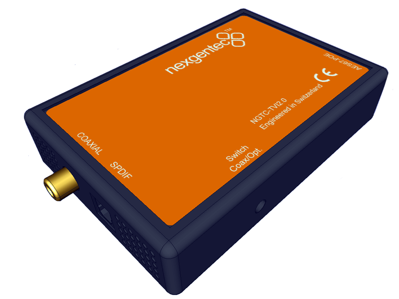
The NGTC-TVI2.0R2 is a Digital to Analog Audio Converter, that has been designed for either marine, residential or professional audio applications. It converts Coaxial or Toslink digital audio signals to analog L/R audio and it is available for connection to an external device, such as an amplifier, via standard RCA-style jacks. This
Converter is small in size and quite easy to install.
AES67 interoperability settings are required for every Dante device that should receive a AES67 stream
To enable your Dante devices to receive an AES67 stream, AES67 interoperability must be enabled. This is done by using Audinate’s Dante Controller, which can be obtained from the Audinate website or any other manufacturer specific software tool.
In Dante controller all your Dante devices that are connected to the network will show up automatically.

To configure the AES67 download latest generation Audio Grid Controller Software. Your PC needs to be connected to the AES67 network and have its addressing set in the same IP range.
Start the software and go to the “Device Config” tab
The AES67 stream of each device needs to be configured to be received by the Dante/AES67 devices
Start the software and go to the “Device Config” tab


Natively the audio routing can be done by using Audinate’s Dante Controller in case if its not auto configured by the DSP’s management software. In Dante Controller all your Dante and AES67 devices that are connected to the network will show up automatically.
The BTI will be shown at the ‘‘Dante Transmitters’’ part, using its multicast address@hostname-HH-HH-HH where ‘‘HH-HH-HH’’ are the last three bytes of the devices MAC address.

| Channel | Assignment |
|---|---|
| 1 | Left Channel |
| 2 | Right Channel |
Welcome to the Firmware section!
If you are not redirected automatically, click here.
The latest generation of TVI2.0R2 features an AES67 daughter board that fully supports AES67, ensuring compatibility with Dante™. Additionally, these devices have mDNS discovery enabled, allowing them to be detected in the Dante Controller, similar to a Dante product.
However, starting with Dante Controller V12, a pop-up message may appear indicating that unlicensed Dante™ products are being used. To address this, the new firmware will disable Dante™ discovery, and all R2 units will be recognized as AES67 devices.

After the reboot, click “Refresh” to update the device list. If the devices appear as expected, you can proceed with the update process.

After the reboot, you need to set the multicast address for AES67 to work. Use the Audio Grid Controller to do this.
Refer to the following instructions to configure it with the AudioGrid controller
The NGTC-TVI2.0 is a Digital to Analog Audio Converter, that has been designed for either marine, residential or professional audio applications. It converts Coaxial or Toslink digital audio signals to analog L/R audio and it is available for connection to an external device, such as an amplifier, via standard RCA-style jacks. This
Converter is small in size and quite easy to install.
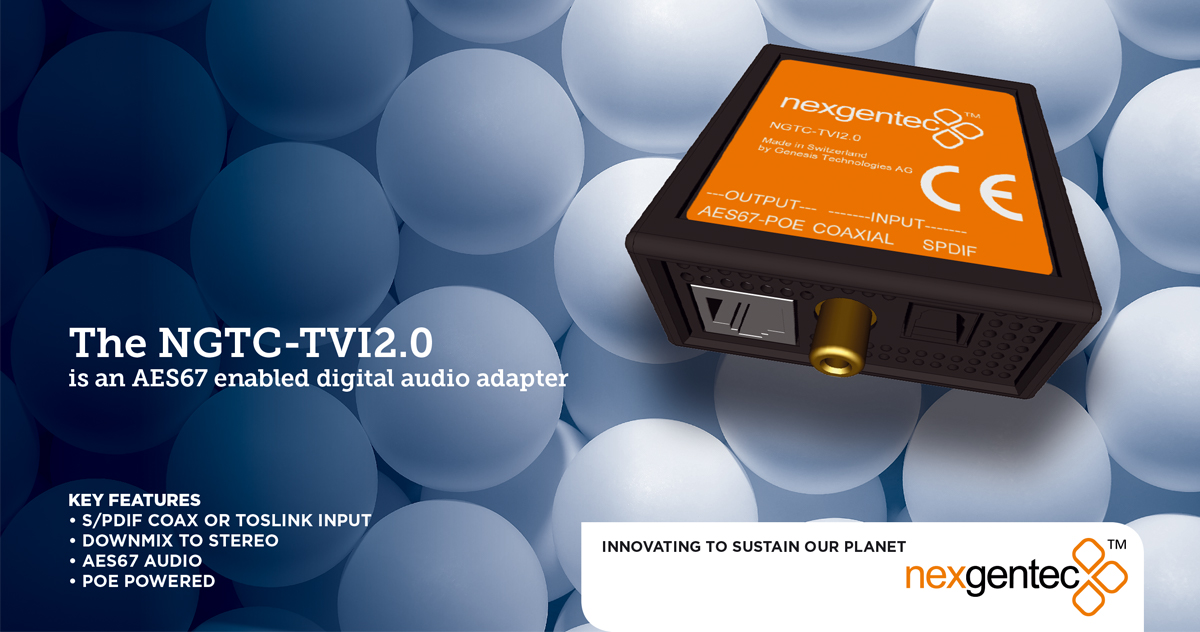
AES67 interoperability settings are required for every Dante device that should receive a AES67 stream
To enable your Dante devices to receive an AES67 stream, AES67 interoperability must be enabled. This is done by using Audinate’s Dante Controller, which can be obtained from the Audinate website or any other manufacturer specific software tool.
In Dante controller all your Dante devices that are connected to the network will show up automatically.

To configure the AES67 network address use the built in Audiolan web UI. Your PC needs to be connected to the AES67 network and have its addressing set in the same IP range.
By default the AES67 network interface is set to DHCP
To avoid an IP conflicts, connect one device after another and change each units IP to a different one
Avoid any special characters and spaces in the device name

The AES67 stream of each device needs to be configured to be received by the Dante/AES67 devices
Avoid any special characters and spaces in the stream name

Natively the audio routing can be done by using Audinate’s Dante Controller in case if its not auto configured by the DSP’s management software. In Dante Controller all your Dante and AES67 devices that are connected to the network will show up automatically.
The BTI will be shown at the ‘‘Dante Transmitters’’ part, using its multicast address@hostname-HH-HH-HH where ‘‘HH-HH-HH’’ are the last three bytes of the devices MAC address.

| Channel | Assignment |
|---|---|
| 1 | Left Channel |
| 2 | Right Channel |
The NGTC-32140PWR is a DanteTM enabled network power amplifier for the nexgentec™ audio distribution solution
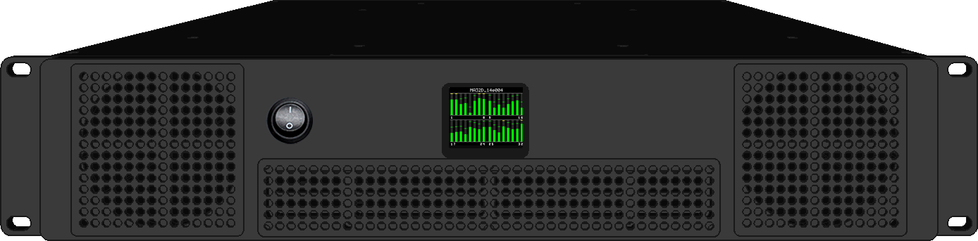
This section describes the communication protocol between the control system and the 32140PWR
| Connection | TCP/HTTP (NGTC-32140PWR is HTTP server), Port 80 |
| Command Format | IP/0CXQRB2XQ3KD7XB/nexgentec.fcgi?action=action¶m=value |
Multiple parameters and values must be sent like: …?action=21&channel=1&name=MySpeaker
All commands must be sent as standard HTTP requests including headers, the server responds with a reply header and a JSON data table
Server will close the connection once replied, to keep the connection open set the keep-alive flag in the request header
Use any browser to test the communication"
| Communication | Action | Parameter | Example |
|---|---|---|---|
| Request | 0 | ||
IP/0CXQRB2XQ3KD7XB/nexgentec.fcgi?action=0 |
|||
| Reply | {“version”: “1.0.0”, “api-version”: “N3”,“fpga-version”: “2.2.0-d51c0cc4-#1040”, | ||
| “serial”: “240818000117”,“type”: 1,“type-string”: “32140PWR”,“channel”: 32} |
| Communication | Action | Parameter | Example |
|---|---|---|---|
| Request | 1 | ||
IP/0CXQRB2XQ3KD7XB/nexgentec.fcgi?action=1 |
|||
| Reply | {“hostname”: “My Amp”} |
| Communication | Action | Parameter | Example |
|---|---|---|---|
| Request | 2 | ||
IP/0CXQRB2XQ3KD7XB/nexgentec.fcgi?action=2&hostname=“MyAmp” |
|||
| Reply | {“hostname”: “MyAmp”} |
| Communication | Action | Parameter | Example |
|---|---|---|---|
| Request | 3 | ||
IP/0CXQRB2XQ3KD7XB/nexgentec.fcgi?action=3 |
|||
| Reply | {“type”: “dhcp”,“ip”: “10.77.178.237”,“subnet”: “255.255.0.0”,“gateway”: “10.77.178.1”} |
| Communication | Action | Parameter | Example |
|---|---|---|---|
| Request | 4 | ||
| type=static/dhcp/auto | |||
| ip=x.x.x.x | |||
| netmask=x.x.x.x | |||
| gateway=x.x.x.x | |||
IP/0CXQRB2XQ3KD7XB/nexgentec.fcgi?action=4&type=static&ip=10.77.178.10&subnet=255.255.0.0&gateway=10.77.178.1 |
|||
| Reply | {“type”: “dhcp”,“ip”: “10.77.178.237”,“subnet”: “255.255.0.0”,“gateway”: “10.77.178.1”} |
| Communication | Action | Parameter | Example |
|---|---|---|---|
| Request | 5 | ||
IP/0CXQRB2XQ3KD7XB/nexgentec.fcgi?action=5 |
|||
| Reply | {“value”: 230} |
| Communication | Action | Parameter | Example |
|---|---|---|---|
| Request | 6 | ||
| value=90-240V | |||
IP/0CXQRB2XQ3KD7XB/nexgentec.fcgi?action=6&value=110 |
|||
| Reply | {“value”: 110} |
| Communication | Action | Parameter | Example |
|---|---|---|---|
| Request | 7 | ||
IP/0CXQRB2XQ3KD7XB/nexgentec.fcgi?action=7 |
|||
| Reply | {“volume”: 0.0} |
| Communication | Action | Parameter | Example |
|---|---|---|---|
| Request | 8 | ||
| volume=-100.0 - 24.0 | |||
IP/0CXQRB2XQ3KD7XB/nexgentec.fcgi?action=6&volume=0 |
|||
| Reply | {“volume”: 0.0} |
| Communication | Action | Parameter | Example |
|---|---|---|---|
| Request | 9 | ||
IP/0CXQRB2XQ3KD7XB/nexgentec.fcgi?action=9 |
|||
| Reply | {“mute”: 1} |
| Communication | Action | Parameter | Example |
|---|---|---|---|
| Request | 10 | ||
| mute=0/1 | |||
IP/0CXQRB2XQ3KD7XB/nexgentec.fcgi?action=10&mute=1 |
|||
| Reply | {“mute”: 1} |
| Communication | Action | Parameter | Example |
|---|---|---|---|
| Request | 11 | ||
IP/0CXQRB2XQ3KD7XB/nexgentec.fcgi?action=11 |
|||
| Reply | {“reduction”: -0.0} |
| Communication | Action | Parameter | Example |
|---|---|---|---|
| Request | 20 | ||
| channel=1-MAX Channel Number | |||
IP/0CXQRB2XQ3KD7XB/nexgentec.fcgi?action=20&channel=1 |
|||
| Reply | {“channel”:1,“name”: “Ch 1”} |
| Communication | Action | Parameter | Example |
|---|---|---|---|
| Request | 21 | ||
| channel=1-MAX Channel Number | |||
| name=MAX 30 Chars | |||
IP/0CXQRB2XQ3KD7XB/nexgentec.fcgi?action=21&channel=1&name=MySpeaker |
|||
| Reply | {“channel”:1,“name”: “MySpeaker”} |
| Communication | Action | Parameter | Example |
|---|---|---|---|
| Request | 22 | ||
| channel=1-MAX Channel Number | |||
IP/0CXQRB2XQ3KD7XB/nexgentec.fcgi?action=22&channel=1 |
|||
| Reply | {“channel”:1,“enable”: 1} |
| Communication | Action | Parameter | Example |
|---|---|---|---|
| Request | 23 | ||
| channel=1-MAX Channel Number, comma seperated if multiple | |||
| enable=1/0 | |||
IP/0CXQRB2XQ3KD7XB/nexgentec.fcgi?action=23&channel=1,2,3,4,5&enable=1 |
|||
| Reply | {“channel”: [1,2,3,4,5],“enable”: 0} |
| Communication | Action | Parameter | Example |
|---|---|---|---|
| Request | 24 | ||
| channel=1-MAX Channel Number | |||
IP/0CXQRB2XQ3KD7XB/nexgentec.fcgi?action=24&channel=1 |
|||
| Reply | {“channel”:1,“volume”: 0.0} |
| Communication | Action | Parameter | Example |
|---|---|---|---|
| Request | 25 | ||
| channel=1-MAX Channel Number | |||
| volume=-72.0 - 24.0 | |||
IP/0CXQRB2XQ3KD7XB/nexgentec.fcgi?action=25&channel=1&volume=1 |
|||
| Reply | {“channel”:1,“volume”: 1.0} |
| Communication | Action | Parameter | Example |
|---|---|---|---|
| Request | 30 | ||
| channel=1-MAX Channel Number | |||
IP/0CXQRB2XQ3KD7XB/nexgentec.fcgi?action=30&channel=1 |
|||
| Reply | {“channel”:1,“peak”: -11.1,“hold”: -9.7,“clip”: 0} |
| Communication | Action | Parameter | Example |
|---|---|---|---|
| Request | 31 | ||
| channel=1-MAX Channel Number | |||
IP/0CXQRB2XQ3KD7XB/nexgentec.fcgi?action=31&channel=1 |
|||
| Reply | {“channel”:1,“status”: 0,“status_text”: “OFF”,“temp”: 38.5} |
| Communication | Action | Parameter | Example |
|---|---|---|---|
| Request | 40 | ||
IP/0CXQRB2XQ3KD7XB/nexgentec.fcgi?action=40 |
|||
| Reply | {“level”: [{ | ||
| “peak”: -10.0,“hold”: -9.3,“clip”: 0}, | |||
| {“peak”: -12.0,“hold”: -11.4,“clip”: 0}, | |||
| … ]} |
| Communication | Action | Parameter | Example |
|---|---|---|---|
| Request | 41 | ||
IP/0CXQRB2XQ3KD7XB/nexgentec.fcgi?action=41 |
|||
| Reply | {“overview”: [ | ||
| { “status”: 0,“status_text”: “OFF”,“temp”: 38.5,“enable”: 0,“volume”: 1.0,“name”: “MySpeaker”}, | |||
| { “status”: 1,“status_text”: “OK”,“temp”: 38.5,“enable”: 1,“volume”: 0.0,“name”: “Ch 2”}, | |||
| … ]} |
| Communication | Action | Parameter | Example |
|---|---|---|---|
| Request | 50 | ||
IP/0CXQRB2XQ3KD7XB/nexgentec.fcgi?action=50 |
|||
| Reply | {“syslog_ip”: “192.168.1.1”,“syslog_port”: “555”} |
| Communication | Action | Parameter | Example |
|---|---|---|---|
| Request | 51 | ||
| syslog_ip=x.x.x.x | |||
| syslog_port=x | |||
IP/0CXQRB2XQ3KD7XB/nexgentec.fcgi?action=action=51 &syslog_ip=192.168.1.1&syslog_port=555 |
|||
| Reply | {“syslog_ip”: “192.168.1.1”,“syslog_port”: “555”} |
| Communication | Action | Parameter | Example |
|---|---|---|---|
| Request | 52 | ||
| number=x | |||
IP/0CXQRB2XQ3KD7XB/nexgentec.fcgi?action=52&number=1 |
|||
| Reply | {“log”: [“Jan 1 01:42:37 32140PWR-000117user.info root: Amp is ok”]} |
Firmware updates can be downloaded directly with the updater tool. If on site no internet is available do not forget to download previously
Download updater
Disable Windows Firewall on the interface which connects to the same network as the amp
Start update software
Select Firmware.
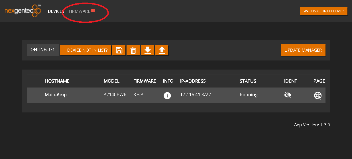
Click on the row for each device to display the firmwares available
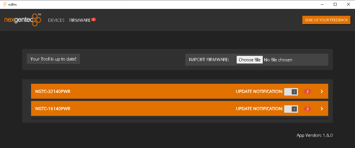
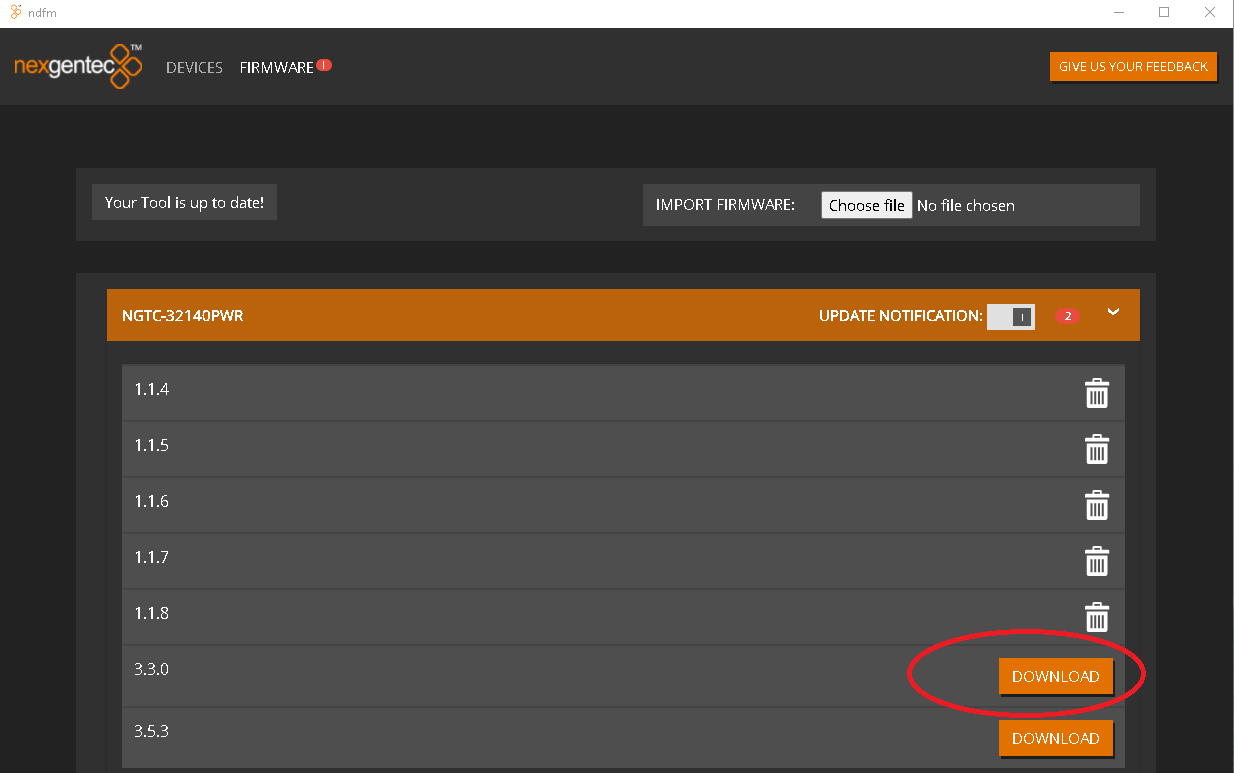
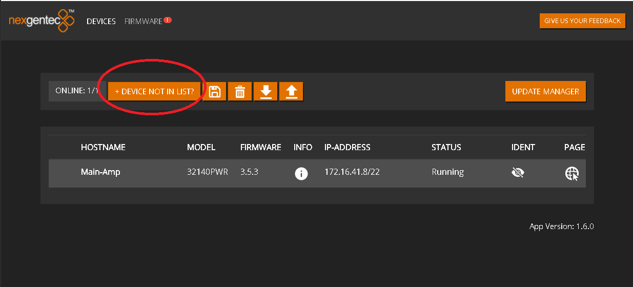
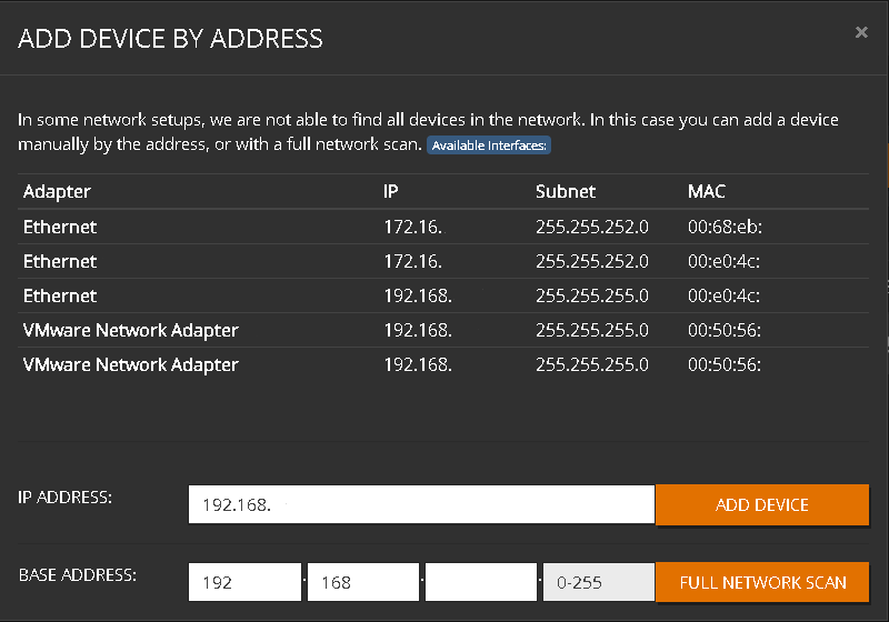
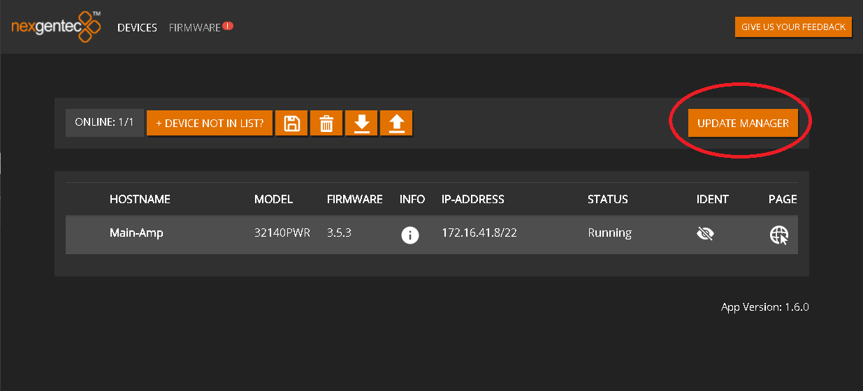
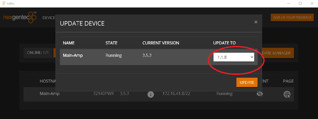
The NGTC-2140PWRR3 is a Dante™ enabled network power amplifier for the nexgentec™ audio distribution solution
Never downgrade to an older ngtOS, as it will result in a factory return of the unit in every case.
If you have multiple units to update, try the update on one and if it’s working as expected, proceed with all others.
You may need help when updating units with ngtOS below version 1.0.13. Ensure that you are inside the office opening hours of Genesis Technologies Switzerland. (8am till 4pm CET +1)
Your unit(s) probably need some special treatment before the update. Please contact Genesis Technologies Switzerland at info@genesis-technologies.ch before you attempt to update.
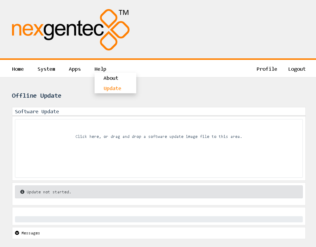
Each installed app can be configured to a certain level via the web interface.
The default login for the web interface is: Username: admin Password: nexgentec
Open a browser and enter the device’s network address in the address bar, then press Enter.
Use the top menu bar to navigate to Apps and select the app to be configured.
Using the top menu bar, navigate to Apps > Amplifier.
Selecting “Files” will open the file browser where you can download and view the log files from the app.
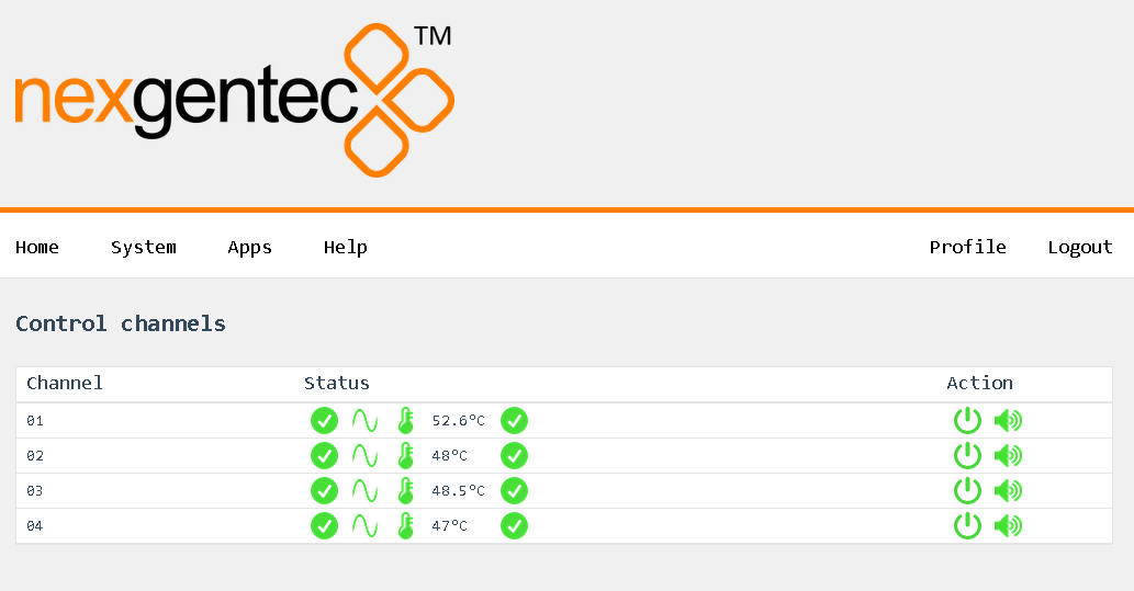
Using the top menu bar, navigate to Apps > API.
Selecting “Files” will open the file browser where you can download and view the log files from the app.
Using the top menu bar, navigate to Apps > Broker.
Selecting “Files” will open the file browser where you can download and view the log files from the app.
Using the top menu bar, navigate to Apps > Broker.
Selecting “Files” will open the file browser where you can download and view the log files from the app.
Using the top menu bar, navigate to Apps > Display.
Selecting “Files” will open the file browser where you can download and view the log files from the app.
Using the top menu bar, navigate to Apps > WebUI.
Selecting “Files” will open the file browser where you can download and view the log files from the app.
Using the top menu bar, navigate to Apps > WebUI.
Selecting “Files” will open the file browser where you can download and view the log files from the app.
All configuration tasks can be performed via the web interface.
The default login for the web interface is: Username: admin Password: nexgentec
Open a browser and enter the device’s network address in the address bar, then press Enter.

Use the top menu bar to navigate to the option you want.
This guide applies to all units running ngtOS >= version 1.0.13 (beta-rc3)
The status of the network connections can be viewed on the status page System > Network > Status
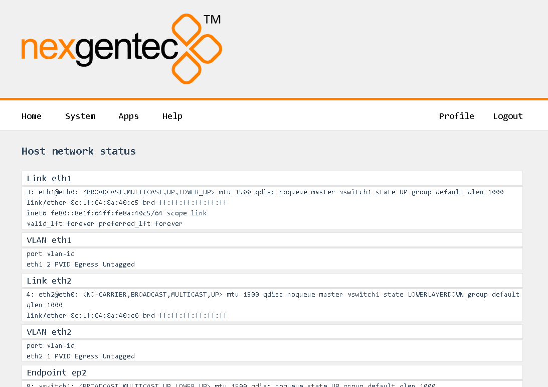
Points to consider:
If things go wrong:
In general, the physical network interfaces and the internal endpoints should be understood as a managed switch infrastructure. Each physical port can take untagged and tagged VLANs, each VLAN can be used to connect an “Endpoint” for Audio and/or Control. Finally, VLANs can be forwarded tagged or untagged between the physical interfaces, keeping the tagging or even untagging during forwarding.
There is no mandatory number of Endpoints. At least one must exist, and it can be a combined one for both audio and control. An arbitrary number of Endpoints for control can exist, but only one for audio.
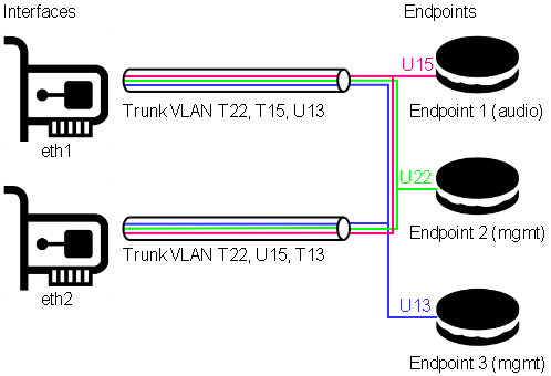 In this example, both physical ports are carrying VLANs 13, 15, and 22.
VLAN 13 is the untagged (native) VLAN on eth1 and gets tagged while flowing towards eth2, and vice versa. It’s also received by Endpoint 3, which is a management endpoint. The IP address (fixed or statically assigned) of Endpoint 3 can be reached on eth1 using no VLAN tag and on eth2 using a VLAN tag 13.
VLAN 15 is the tagged VLAN on eth1 and gets untagged while flowing towards eth2 (native), and vice versa. It’s also received by Endpoint 1, which is the audio endpoint. The IP address (fixed or statically assigned) of Endpoint 1 can be reached on eth1 using VLAN tag 15 and on eth2 using no VLAN tag.
VLAN 22 is a tagged VLAN which flows over both physical interfaces. It’s also received by Endpoint 2, which is a management endpoint. The IP address (fixed or statically assigned) of Endpoint 2 can be reached on any of the two physical interfaces using a VLAN tag 22.
The front panel display shows the current network configuration, including how to access the shown IP address. If multiple endpoints exist, the line scrolls every 5 seconds to display all endpoints.
Syntax: physical[:Tagged VLAN]>Endpoint name > IP Address (CIDR notation).
Following the example above:
Select in the top menu System > Network > Settings
Continuing with the example above, this would look like:
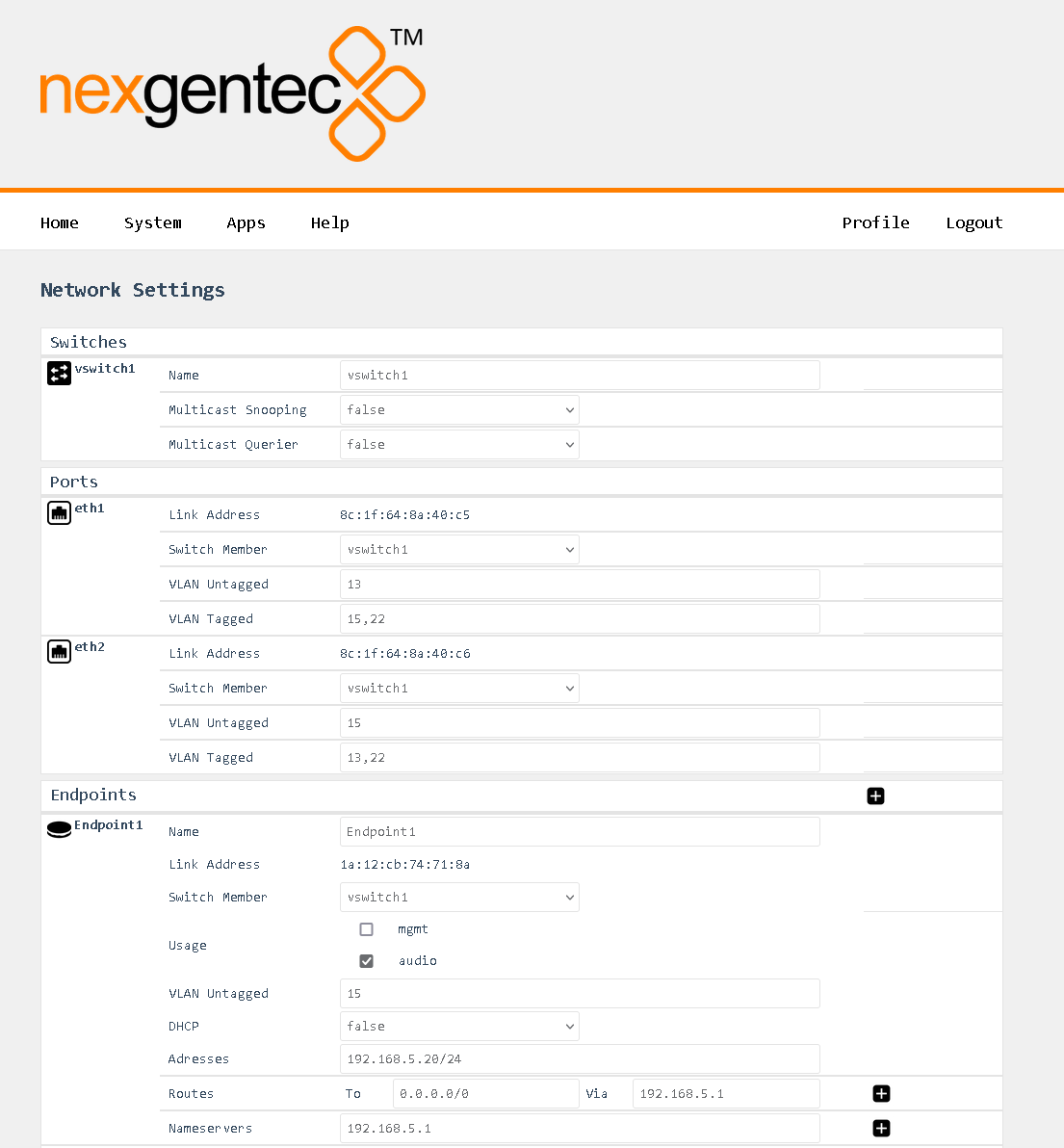
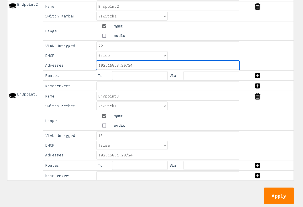
Control the Amplifier over TCP and HTTP using JSON-RPC 2.0
This is a preliminary api documentation, subject to change
This section describes the communication protocol between the control system and the 4140PWRR3 using RPC calls using the JSON-RPC 2.0 protocol
Commands must be formatted as defined in the JSON-RPC 2.0 protocol
All commands sent over TCP transport must end with <LF>
All replies are formatted as defined in the JSON-RPC 2.0 protocol
All replies over TCP transport end up with <LF>
<LF> stands for “line feed”, corresponding hex is 0x0A
JSON-RPC 2.0 commands can flow over different transport protocols, they need to be enabled in the config file of the installed api service. Per default they might not be enabled.
| Transport | Config | Datatype | Example | Supported Versions |
|---|---|---|---|---|
| TCP | jrpc2TCPInterface | string | eth1 | >v1.0.1 |
| TCP | jrpc2TCPPort | int | 64823 | >v1.0.1 |
| TCP | jrpc2HTTPInterface | string | eth1 | >v1.0.1 |
| TCP | jrpc2HTTPPort | int | 64880 | >v1.0.1 |
In subsequent pages all methods are described that can be used.
All JSON-RPC 2.0 services do support asynchronous message processing. 3rd party control Systems must keep tracking of the id’s to determine whether a request was successful or not
Any TCP capable application can be used to test commands. Do not forget to end up with <LF>
The body of the HTTP POST request must contain the complete JSON-RPC request message, encoded with Content-Type: application/json. Either a single request object or a list of request objects is supported. If the request completes, whether or not there is an error, the HTTP response is 200 (OK) for ordinary requests or 204 (No Response) for notifications, and the response body contains the JSON-RPC response. If the HTTP request method is not “POST”, 4140PWRR3 reports 405 (Method Not Allowed). If the Content-Type is not application/json, 4140PWRR3 reports 415 (Unsupported Media Type).
Test from a linux shell:
curl -i -X POST -H ‘Content-Type: application/json’ -d ‘{“jsonrpc”:“2.0”,“id”:1,“method”:“rpc.serverInfo”}’ http://host:64880
Enable or disable, mute or unmute a amplifier channel
A hardware limitation only allows stereo channel pairs to be switched on the 2140pwrr3.
A hardware limitation only allows stereo channel pairs to be muted on the 2140pwrr3.
| Method | Param | Value | Comment | Supported Versions |
|---|---|---|---|---|
| amplifier.channelSet | >v1.0.1 | |||
| channel | 1,2,3,4 | Channel selection | >v1.0.1 | |
| power | 0,1 | Power on (1) or off (0) | >v1.0.1 | |
| mute | 0,1 | Mute (1) or unmute (0) | >v1.0.1 | |
| amplifier.channel.set | >=v1.0.14 | |||
| channel | 1,2,3,4 | Channel selection | >=v1.0.14 | |
| power | 0,1 | Power on (1) or off (0) | >=v1.0.14 | |
| mute | 0,1 | Mute (1) or unmute (0) | >=v1.0.14 |
{"jsonrpc":"2.0","id":1,"method":"amplifier.channelSet","params":{"channel":1,"power":1}}

{"jsonrpc":"2.0","id":1,"method":"amplifier.channel.set","params":{"channel":1,"power":1}}{"jsonrpc":"2.0","id":1,"method":"amplifier.channelSet","params":{"channel":1,"power":1}}
{"jsonrpc":"2.0","id":1,"method":"amplifier.channel.set","params":{"channel":1,"power":1}}{"jsonrpc":"2.0","id":1,"method":"amplifier.channelSet","params":{"channel":1,"mute":1}}
{"jsonrpc":"2.0","id":1,"method":"amplifier.channel.set","params":{"channel":1,"mute":1}}{"jsonrpc":"2.0","id":1,"method":"amplifier.channelSet","params":{"channel":1,"power":1,"mute":0}}
{"jsonrpc":"2.0","id":1,"method":"amplifier.channel.set","params":{"channel":1,"power":1,"mute":0}}| Result | Comment | |
|---|---|---|
| null | null means acknowledged, no error |
{"jsonrpc":"2.0","id":1,"result":null}Get the status of an amplifier channel
| Method | Param | Value | Comment | Supported Versions |
|---|---|---|---|---|
| amplifier.channelGet | >v1.0.1 | |||
| amplifier.channel.get | >=v1.0.14 | |||
| channel | 1,2,3,4 | Channel selection | >v1.0.1 |
{"jsonrpc":"2.0","id":1,"method":"amplifier.channelGet","params":{"channel":1}}
{"jsonrpc":"2.0","id":1,"method":"amplifier.channel.get","params":{"channel":1}}| Result | Key | Comment |
|---|---|---|
| channel status | ||
| power | 1 if channel was powered on, 0 if channel was powered off | |
| mute | 1 if channel was muted, 0 if channel was unmuted | |
| error | null if no error on channel otherwise error message | |
| powerStatus | 1 if channel is powered, otherwise 0 | |
| clip | 1 if channel is clipping, otherwise 0 | |
| temp | Temperature in °C |
{"jsonrpc":"2.0","id":1,"result":{"channel":1,"power":1,"mute":0,"error":null,"powerStatus":1,"clip":0,"temp":42.3}}Subscribe all amplifier channels status push messages
Enable push status messages
Pushed status messages having the same format as channelGet replies
Push messages over HTTP transport are not supported
| Method | Param | Value | Comment | Supported Versions |
|---|---|---|---|---|
| amplifier.channelsSubscribe | >v1.0.1 | |||
| amplifier.channels.subscribe | >v1.0.14 |
{"jsonrpc":"2.0","id":1,"method":"amplifier.channelsSubscribe"}
{"jsonrpc":"2.0","id":1,"method":"amplifier.channels.subscribe"}| Result | Comment | |
|---|---|---|
| null | null means acknowledged, no error |
{"jsonrpc":"2.0","id":1,"result":null}Unsubscribe all amplifier channels status push messages
| Method | Param | Value | Comment | Supported Versions |
|---|---|---|---|---|
| amplifier.channelsUnsubscribe | >v1.0.1 | |||
| amplifier.channels.unsubscribe | >=v1.0.14 |
{"jsonrpc":"2.0","id":1,"method":"amplifier.channelsUnsubscribe"}
{"jsonrpc":"2.0","id":1,"method":"amplifier.channels.unsubscribe"}| Result | Comment | |
|---|---|---|
| null | null means acknowledged, no error |
{"jsonrpc":"2.0","id":1,"result":null}Get the log level for the 2140pwrr3 service running on the 2140pwrr3
| Method | Param | Value | Comment | Supported Versions |
|---|---|---|---|---|
| 2140pwrr3.app.log.level.get | >=v1.0.14 |
{"jsonrpc":"2.0","id":1,"method":"2140pwrr3.app.log.level.get"}| Result | Comment | |
|---|---|---|
| x | Active log level |
{"jsonrpc":"2.0","id":20,"result":{"level":3}}Set the log level for sdm and associated processes
| Method | Param | Value | Comment | Supported Versions |
|---|---|---|---|---|
| 2140pwrr3.app.log.level.set | level | 0-7 | Log level to set | >=v1.0.14 |
{"jsonrpc":"2.0","id":1,"method":"2140pwrr3.app.log.level.set","params":{"level":6}| Result | Comment | |
|---|---|---|
| null | null means acknowledged, no error |
{"jsonrpc":"2.0","id":1,"result":null}Get the log level for the api service running on the api
| Method | Param | Value | Comment | Supported Versions |
|---|---|---|---|---|
| api.app.log.level.get | >=v1.0.14 |
{"jsonrpc":"2.0","id":1,"method":"api.app.log.level.get"}| Result | Comment | |
|---|---|---|
| x | Active log level |
{"jsonrpc":"2.0","id":20,"result":{"level":3}}Set the log level
| Method | Param | Value | Comment | Supported Versions |
|---|---|---|---|---|
| api.app.log.level.set | level | 0-7 | Log level to set | >=v1.0.14 |
{"jsonrpc":"2.0","id":1,"method":"api.app.log.level.set","params":{"level":6}| Result | Comment | |
|---|---|---|
| null | null means acknowledged, no error |
{"jsonrpc":"2.0","id":1,"result":null}Get the log level for the api service running on the api
| Method | Param | Value | Comment | Supported Versions |
|---|---|---|---|---|
| diplay.backlight.level.get | >=v1.0.14 |
{"jsonrpc":"2.0","id":1,"method":"diplay.backlight.level.get"}| Result | Comment | |
|---|---|---|
| x | Active backlight level |
{"jsonrpc":"2.0","id":20,"result":{"level":3}}Set the backlight level
| Method | Param | Value | Comment | Supported Versions |
|---|---|---|---|---|
| diplay.backlight.level.set | level | 0-255 | Level to set | >=v1.0.14 |
{"jsonrpc":"2.0","id":1,"method":"diplay.backlight.level.set","params":{"level":6}| Result | Comment | |
|---|---|---|
| null | null means acknowledged, no error |
{"jsonrpc":"2.0","id":1,"result":null}Get all supported RCP methods
| Method | Param | Value | Comment | Supported Versions |
|---|---|---|---|---|
| rpc.serverInfo | >1.0.1 | |||
| rpc.server.info.get | >=1.0.14 |
{"jsonrpc":"2.0","id":1,"method":"rpc.serverInfo"}
{"jsonrpc":"2.0","id":1,"method":"rpc.server.info.get"}| Result | Key | Comment |
|---|---|---|
| methods | All supported methods that can be used by a 3rd party control system | |
| counters | Server counters | |
| startTime | Server start time |
{
"result": {
"startTime": "2024-04-11T08:06:23.391135102Z",
"metrics": {
"bytes_written": 0,
"rpc_requests": 1,
"bytes_read": 55,
"notifications_pushed": 0,
"rpc_errors": 0,
"servers_active": 2,
"calls_pushed": 0
},
"methods": [
"2140pwrr3-cf11.app.log.level.get","2140pwrr3-cf11.app.log.level.set","2140pwrr3-cf11.app.version.get","2140pwrr3.app.log.level.get","2140pwrr3.app.log.level.set","2140pwrr3.app.version.get","2140pwrr3.appLogLevelGet","2140pwrr3.appLogLevelSet","2140pwrr3.appVersionGet","amplifier.channel.get","amplifier.channel.set","amplifier.channelGet","amplifier.channelSet","amplifier.channels.subscribe","amplifier.channels.unsubscribe","amplifier.channelsSubscribe","amplifier.channelsUnsubscribe","api.app.log.level.get","api.app.log.level.set","api.app.version.get","api.appLogLevelGet","api.appLogLevelSet","api.appVersionGet","display.backlight.level.get","display.backlight.level.set","rpc.server.info.get","rpc.serverInfo","webui.app.log.level.get","webui.app.log.level.set","webui.app.version.get"]
},
"id": 1,
"jsonrpc": "2.0"
}The NGTC-4140PWRR3 is a Dante™ enabled network power amplifier for the nexgentec™ audio distribution solution
Never downgrade to an older ngtOS, as it will result in a factory return of the unit in every case.
If you have multiple units to update, try the update on one and if it’s working as expected, proceed with all others.
You may need help when updating units with ngtOS below version 1.0.13. Ensure that you are inside the office opening hours of Genesis Technologies Switzerland. (8am till 4pm CET +1)
Your unit(s) probably need some special treatment before the update. Please contact Genesis Technologies Switzerland at info@genesis-technologies.ch before you attempt to update.

Each installed app can be configured to a certain level via the web interface.
The default login for the web interface is: Username: admin Password: nexgentec
Open a browser and enter the device’s network address in the address bar, then press Enter.

Use the top menu bar to navigate to Apps and select the app to be configured.
Using the top menu bar, navigate to Apps > Amplifier.
Selecting “Files” will open the file browser where you can download and view the log files from the app.

Using the top menu bar, navigate to Apps > API.
Selecting “Files” will open the file browser where you can download and view the log files from the app.
Using the top menu bar, navigate to Apps > Broker.
Selecting “Files” will open the file browser where you can download and view the log files from the app.
Using the top menu bar, navigate to Apps > Broker.
Selecting “Files” will open the file browser where you can download and view the log files from the app.
Using the top menu bar, navigate to Apps > Display.
Selecting “Files” will open the file browser where you can download and view the log files from the app.
Using the top menu bar, navigate to Apps > WebUI.
Selecting “Files” will open the file browser where you can download and view the log files from the app.
Using the top menu bar, navigate to Apps > WebUI.
Selecting “Files” will open the file browser where you can download and view the log files from the app.
All configuration tasks can be performed via the web interface.
The default login for the web interface is: Username: admin Password: nexgentec
Open a browser and enter the device’s network address in the address bar, then press Enter.

Use the top menu bar to navigate to the option you want.
This guide applies to all units running ngtOS >= version 1.0.13 (beta-rc3)
The status of the network connections can be viewed on the status page System > Network > Status

Points to consider:
If things go wrong:
In general, the physical network interfaces and the internal endpoints should be understood as a managed switch infrastructure. Each physical port can take untagged and tagged VLANs, each VLAN can be used to connect an “Endpoint” for Audio and/or Control. Finally, VLANs can be forwarded tagged or untagged between the physical interfaces, keeping the tagging or even untagging during forwarding.
 In this example, both physical ports are carrying VLANs 13, 15, and 22.
VLAN 13 is the untagged (native) VLAN on eth1 and gets tagged while flowing towards eth2, and vice versa. It’s also received by Endpoint 3, which is a management endpoint. The IP address (fixed or statically assigned) of Endpoint 3 can be reached on eth1 using no VLAN tag and on eth2 using a VLAN tag 13.
VLAN 15 is the tagged VLAN on eth1 and gets untagged while flowing towards eth2 (native), and vice versa. It’s also received by Endpoint 1, which is the audio endpoint. The IP address (fixed or statically assigned) of Endpoint 1 can be reached on eth1 using VLAN tag 15 and on eth2 using no VLAN tag.
VLAN 22 is a tagged VLAN which flows over both physical interfaces. It’s also received by Endpoint 2, which is a management endpoint. The IP address (fixed or statically assigned) of Endpoint 2 can be reached on any of the two physical interfaces using a VLAN tag 22.
The front panel display shows the current network configuration, including how to access the shown IP address. If multiple endpoints exist, the line scrolls every 5 seconds to display all endpoints.
Syntax: physical[:Tagged VLAN]>Endpoint name > IP Address (CIDR notation).
Following the example above:
Select in the top menu System > Network > Settings
Continuing with the example above, this would look like:


You can view the status of the time on the status page by navigating to System > Time > Status.
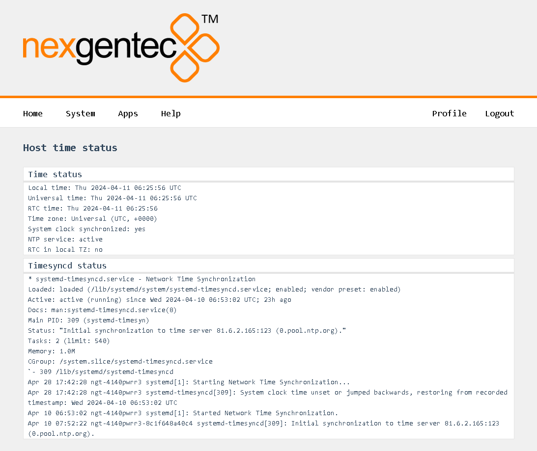
Select in the top menu System > Network > Settings
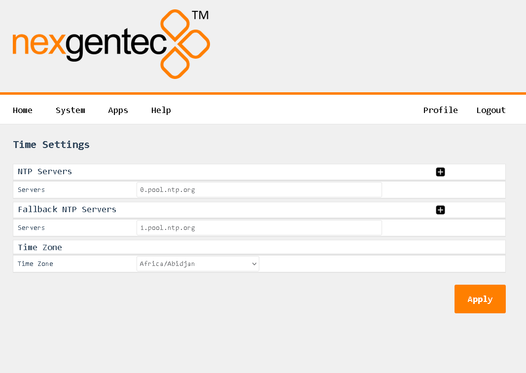
Control the Amplifier over TCP and HTTP using JSON-RPC 2.0
This is a preliminary api documentation, subject to change
This section describes the communication protocol between the control system and the 4140PWRR3 using RPC calls using the JSON-RPC 2.0 protocol
Commands must be formatted as defined in the JSON-RPC 2.0 protocol
All commands sent over TCP transport must end with <LF>
All replies are formatted as defined in the JSON-RPC 2.0 protocol
All replies over TCP transport end up with <LF>
<LF> stands for “line feed”, corresponding hex is 0x0A
JSON-RPC 2.0 commands can flow over different transport protocols, they need to be enabled in the config file of the installed api service. Per default they might not be enabled.
| Transport | Config | Datatype | Example | Supported Versions |
|---|---|---|---|---|
| TCP | jrpc2TCPInterface | string | eth1 | >v1.0.1 |
| TCP | jrpc2TCPPort | int | 64823 | >v1.0.1 |
| TCP | jrpc2HTTPInterface | string | eth1 | >v1.0.1 |
| TCP | jrpc2HTTPPort | int | 64880 | >v1.0.1 |
In subsequent pages all methods are described that can be used.
All JSON-RPC 2.0 services do support asynchronous message processing. 3rd party control Systems must keep tracking of the id’s to determine whether a request was successful or not
Any TCP capable application can be used to test commands. Do not forget to end up with <LF>
The body of the HTTP POST request must contain the complete JSON-RPC request message, encoded with Content-Type: application/json. Either a single request object or a list of request objects is supported. If the request completes, whether or not there is an error, the HTTP response is 200 (OK) for ordinary requests or 204 (No Response) for notifications, and the response body contains the JSON-RPC response. If the HTTP request method is not “POST”, 4140PWRR3 reports 405 (Method Not Allowed). If the Content-Type is not application/json, 4140PWRR3 reports 415 (Unsupported Media Type).
Test from a linux shell:
curl -i -X POST -H ‘Content-Type: application/json’ -d ‘{“jsonrpc”:“2.0”,“id”:1,“method”:“rpc.serverInfo”}’ http://host:64880
Enable or disable, mute or unmute a amplifier channel
A hardware limitation only allows stereo channel pairs to be switched on the 4140PWRR3.
A hardware limitation only allows stereo channel pairs to be muted on the 4140PWRR3.
| Method | Param | Value | Comment | Supported Versions |
|---|---|---|---|---|
| amplifier.channelSet | >v1.0.1 | |||
| channel | 1,2,3,4 | Channel selection | >v1.0.1 | |
| power | 0,1 | Power on (1) or off (0) | >v1.0.1 | |
| mute | 0,1 | Mute (1) or unmute (0) | >v1.0.1 | |
| amplifier.channel.set | >=v1.0.14 | |||
| channel | 1,2,3,4 | Channel selection | >=v1.0.14 | |
| power | 0,1 | Power on (1) or off (0) | >=v1.0.14 | |
| mute | 0,1 | Mute (1) or unmute (0) | >=v1.0.14 |
{"jsonrpc":"2.0","id":1,"method":"amplifier.channelSet","params":{"channel":1,"power":1}}

{"jsonrpc":"2.0","id":1,"method":"amplifier.channel.set","params":{"channel":1,"power":1}}{"jsonrpc":"2.0","id":1,"method":"amplifier.channelSet","params":{"channel":1,"power":1}}
{"jsonrpc":"2.0","id":1,"method":"amplifier.channel.set","params":{"channel":1,"power":1}}{"jsonrpc":"2.0","id":1,"method":"amplifier.channelSet","params":{"channel":1,"mute":1}}
{"jsonrpc":"2.0","id":1,"method":"amplifier.channel.set","params":{"channel":1,"mute":1}}{"jsonrpc":"2.0","id":1,"method":"amplifier.channelSet","params":{"channel":1,"power":1,"mute":0}}
{"jsonrpc":"2.0","id":1,"method":"amplifier.channel.set","params":{"channel":1,"power":1,"mute":0}}| Result | Comment | |
|---|---|---|
| null | null means acknowledged, no error |
{"jsonrpc":"2.0","id":1,"result":null}Get the status of an amplifier channel
| Method | Param | Value | Comment | Supported Versions |
|---|---|---|---|---|
| amplifier.channelGet | >v1.0.1 | |||
| amplifier.channel.get | >=v1.0.14 | |||
| channel | 1,2,3,4 | Channel selection | >v1.0.1 |
{"jsonrpc":"2.0","id":1,"method":"amplifier.channelGet","params":{"channel":1}}

{"jsonrpc":"2.0","id":1,"method":"amplifier.channel.get","params":{"channel":1}}| Result | Key | Comment |
|---|---|---|
| channel status | ||
| power | 1 if channel was powered on, 0 if channel was powered off | |
| mute | 1 if channel was muted, 0 if channel was unmuted | |
| error | null if no error on channel otherwise error message | |
| powerStatus | 1 if channel is powered, otherwise 0 | |
| clip | 1 if channel is clipping, otherwise 0 | |
| temp | Temperature in °C |
{"jsonrpc":"2.0","id":1,"result":{"channel":1,"power":1,"mute":0,"error":null,"powerStatus":1,"clip":0,"temp":42.3}}Subscribe all amplifier channels status push messages
Enable push status messages
Pushed status messages having the same format as channelGet replies
Push messages over HTTP transport are not supported
| Method | Param | Value | Comment | Supported Versions |
|---|---|---|---|---|
| amplifier.channelsSubscribe | >v1.0.1 | |||
| amplifier.channels.subscribe | >v1.0.14 |
{"jsonrpc":"2.0","id":1,"method":"amplifier.channelsSubscribe"}

{"jsonrpc":"2.0","id":1,"method":"amplifier.channels.subscribe"}| Result | Comment | |
|---|---|---|
| null | null means acknowledged, no error |
{"jsonrpc":"2.0","id":1,"result":null}Unsubscribe all amplifier channels status push messages
| Method | Param | Value | Comment | Supported Versions |
|---|---|---|---|---|
| amplifier.channelsUnsubscribe | >v1.0.1 | |||
| amplifier.channels.unsubscribe | >=v1.0.14 |
{"jsonrpc":"2.0","id":1,"method":"amplifier.channelsUnsubscribe"}

{"jsonrpc":"2.0","id":1,"method":"amplifier.channels.unsubscribe"}| Result | Comment | |
|---|---|---|
| null | null means acknowledged, no error |
{"jsonrpc":"2.0","id":1,"result":null}Get the log level for the 4140pwrr3 service running on the 4140pwrr3
| Method | Param | Value | Comment | Supported Versions |
|---|---|---|---|---|
| 4140pwrr3.app.log.level.get | >=v1.0.14 |
{"jsonrpc":"2.0","id":1,"method":"4140pwrr3.app.log.level.get"}| Result | Comment | |
|---|---|---|
| x | Active log level |
{"jsonrpc":"2.0","id":20,"result":{"level":3}}Set the log level for sdm and associated processes
| Method | Param | Value | Comment | Supported Versions |
|---|---|---|---|---|
| 4140pwrr3.app.log.level.set | level | 0-7 | Log level to set | >=v1.0.14 |
{"jsonrpc":"2.0","id":1,"method":"4140pwrr3.app.log.level.set","params":{"level":6}| Result | Comment | |
|---|---|---|
| null | null means acknowledged, no error |
{"jsonrpc":"2.0","id":1,"result":null}Get the log level for the api service running on the api
| Method | Param | Value | Comment | Supported Versions |
|---|---|---|---|---|
| api.app.log.level.get | >=v1.0.14 |
{"jsonrpc":"2.0","id":1,"method":"api.app.log.level.get"}| Result | Comment | |
|---|---|---|
| x | Active log level |
{"jsonrpc":"2.0","id":20,"result":{"level":3}}Set the log level
| Method | Param | Value | Comment | Supported Versions |
|---|---|---|---|---|
| api.app.log.level.set | level | 0-7 | Log level to set | >=v1.0.14 |
{"jsonrpc":"2.0","id":1,"method":"api.app.log.level.set","params":{"level":6}| Result | Comment | |
|---|---|---|
| null | null means acknowledged, no error |
{"jsonrpc":"2.0","id":1,"result":null}Get the log level for the api service running on the api
| Method | Param | Value | Comment | Supported Versions |
|---|---|---|---|---|
| diplay.backlight.level.get | >=v1.0.14 |
{"jsonrpc":"2.0","id":1,"method":"diplay.backlight.level.get"}| Result | Comment | |
|---|---|---|
| x | Active backlight level |
{"jsonrpc":"2.0","id":20,"result":{"level":3}}Set the backlight level
| Method | Param | Value | Comment | Supported Versions |
|---|---|---|---|---|
| diplay.backlight.level.set | level | 0-255 | Level to set | >=v1.0.14 |
{"jsonrpc":"2.0","id":1,"method":"diplay.backlight.level.set","params":{"level":6}| Result | Comment | |
|---|---|---|
| null | null means acknowledged, no error |
{"jsonrpc":"2.0","id":1,"result":null}Get all supported RCP methods
| Method | Param | Value | Comment | Supported Versions |
|---|---|---|---|---|
| rpc.serverInfo | >1.0.1 | |||
| rpc.server.info.get | >=1.0.14 |
{"jsonrpc":"2.0","id":1,"method":"rpc.serverInfo"}

{"jsonrpc":"2.0","id":1,"method":"rpc.server.info.get"}| Result | Key | Comment |
|---|---|---|
| methods | All supported methods that can be used by a 3rd party control system | |
| counters | Server counters | |
| startTime | Server start time |
{
  "result": {
    "startTime": "2024-04-11T08:06:23.391135102Z",
    "metrics": {
      "bytes_written": 0,
      "rpc_requests": 1,
      "bytes_read": 55,
      "notifications_pushed": 0,
      "rpc_errors": 0,
      "servers_active": 2,
      "calls_pushed": 0
    },
    "methods": [
      "4140pwrr3-cf11.app.log.level.get","4140pwrr3-cf11.app.log.level.set","4140pwrr3-cf11.app.version.get","4140pwrr3.app.log.level.get","4140pwrr3.app.log.level.set","4140pwrr3.app.version.get","4140pwrr3.appLogLevelGet","4140pwrr3.appLogLevelSet","4140pwrr3.appVersionGet","amplifier.channel.get","amplifier.channel.set","amplifier.channelGet","amplifier.channelSet","amplifier.channels.subscribe","amplifier.channels.unsubscribe","amplifier.channelsSubscribe","amplifier.channelsUnsubscribe","api.app.log.level.get","api.app.log.level.set","api.app.version.get","api.appLogLevelGet","api.appLogLevelSet","api.appVersionGet","display.backlight.level.get","display.backlight.level.set","rpc.server.info.get","rpc.serverInfo","webui.app.log.level.get","webui.app.log.level.set","webui.app.version.get"]
  },
  "id": 1,
  "jsonrpc": "2.0"
}
SDM is a Dante™ and AES67 enabled “software defined matrix” for nexgentec™ audio distribution solution or any other solution that uses Dante™ and/or AES67
* Depends on hardware resources.
** Depends on mDNS limitations, DAPI limitations and hardware resource availability. Audinate recommends no more than 300 devices in a system.
NGT-SDM-A32 is limited to up to 32 Dante™ devices
NGT-SDM-A64 is limited to up to 64 Dante™ devices
NGT-SDM-AUNL is intended to work with up to 2500 devices, more available on request

SDM can eavesdrop on communications with Symetrix Symnet devices and act on commands accordingly Together with predefined sources and destinations in configuration files, simple control numbers are used to select sources
Lets take as example that we are connected to a DSP and listen on control number 5001
All configuration tasks can be done over the web interface
Web interface default login
admin / nexgentec
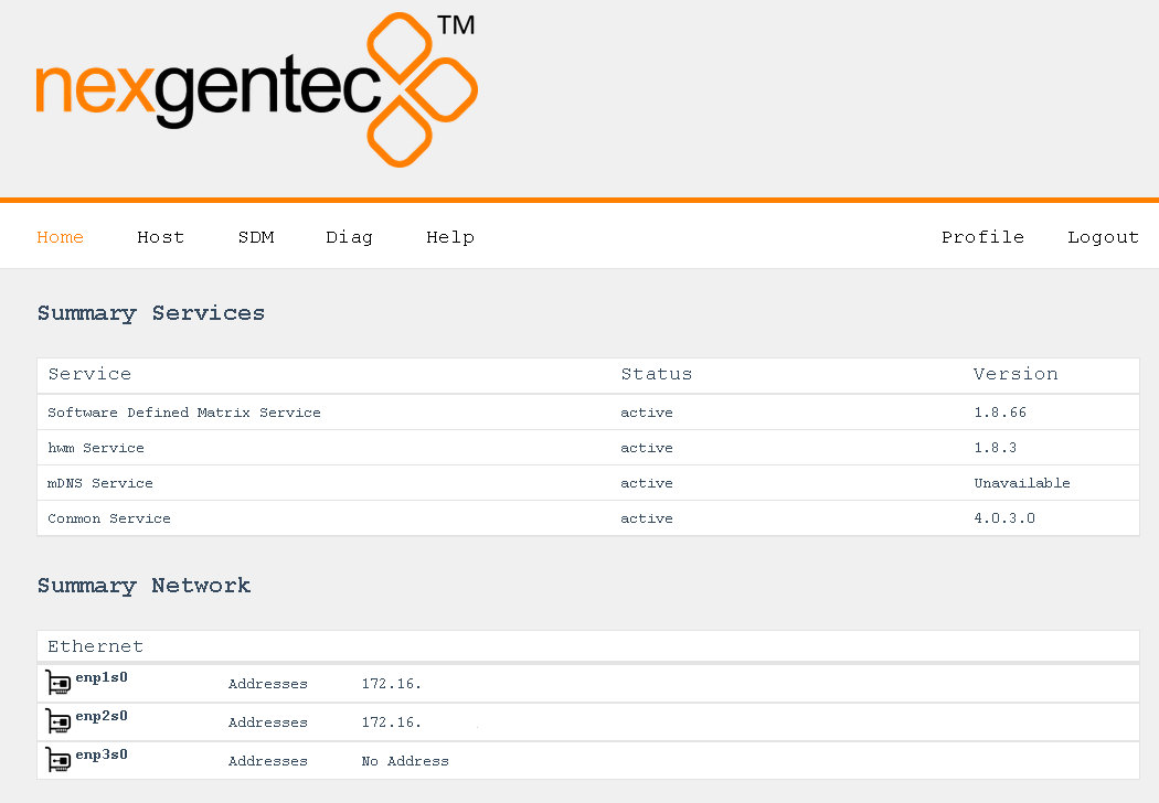
Use the top menu bar to navigate to the option you want
The status of the network connections can be viewed on the status page Host > Network > Status
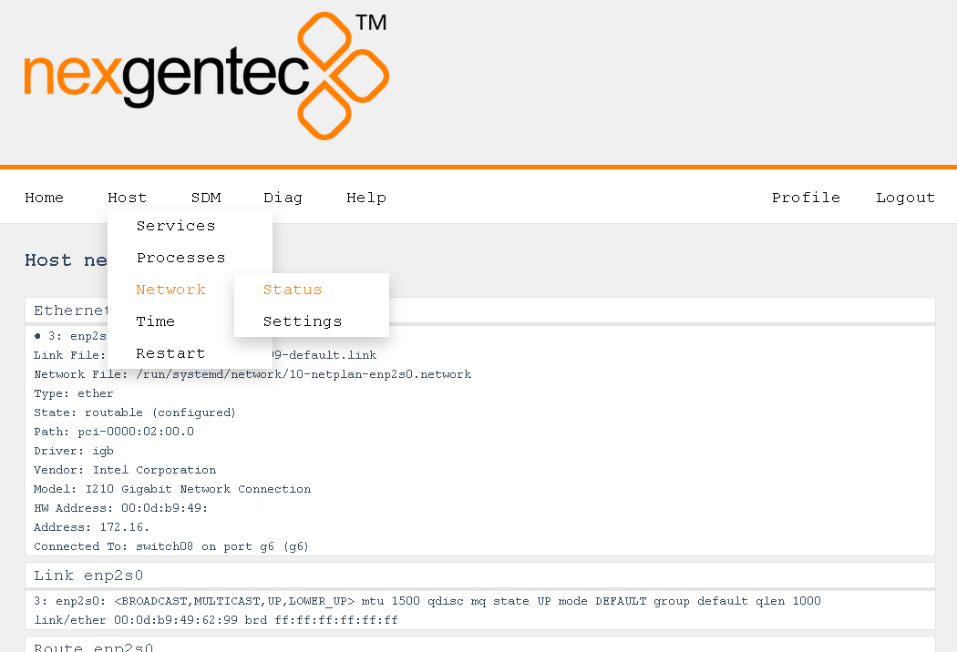
This is like the simplest configuration. Our interface is the first, enp1s0. All you have to do is:
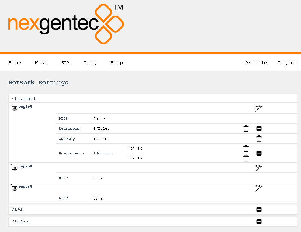
In this scenario we use the Ethernet interface enp1s0 for control and Ethernet interface enp2s0 for Dante™
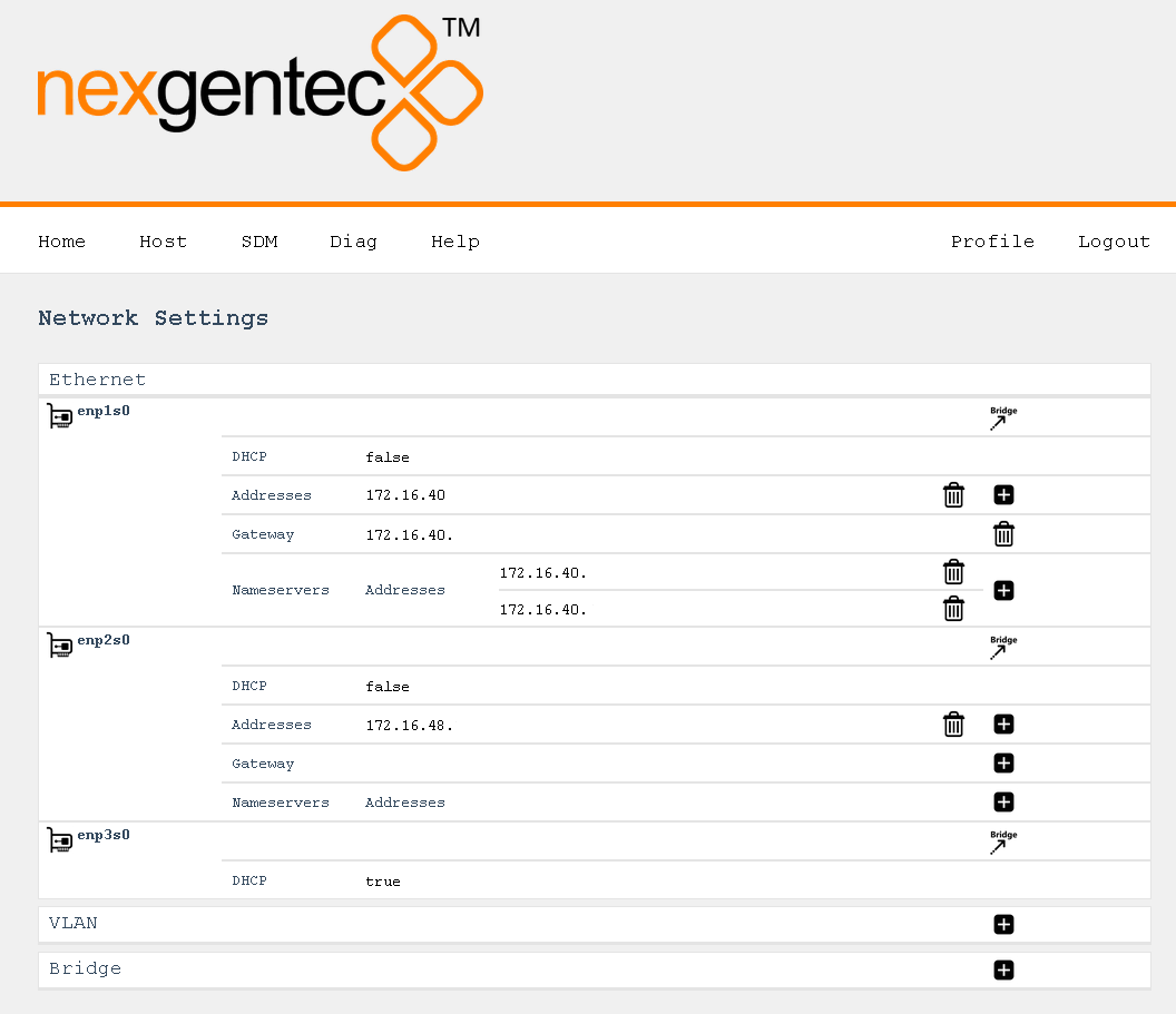
We would like to use the Ethernet interface enp1s0 for control and the VLAN 10 on Ethernet interface enp1s0 for Dante™
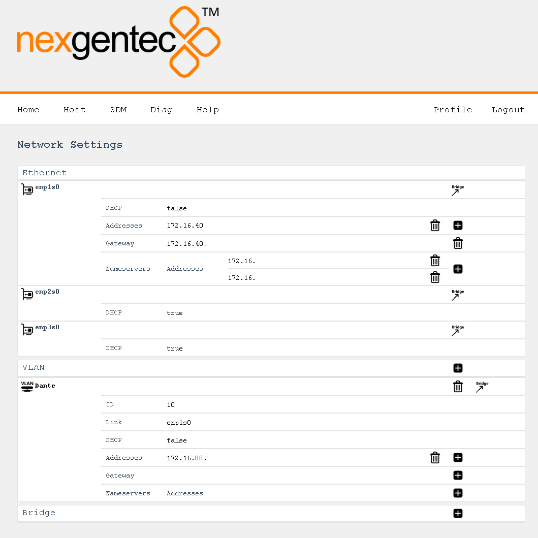
Network configuration be done on the settings page Host > Network > Settings
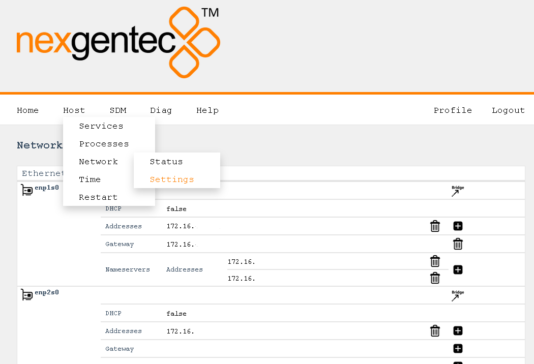
This is not an end consumer product. It requires qualified personnel to be installed If you screw up the settings the hardware have to be sent back to the manufacturer, there is no way back
Points you should pay attention to
Oops, I did it again!
All interfaces are on DHCP if no static address is present
Network settings page uses JavaScript Please activate it in your browser and deactivate popup blockers
All available Ethernet connections found on the hardware are listed. Any Ethernet interface can be added to a new bridge using the bridge symbol. The new bridge will overtake all settings from the Ethernet interface
VLAN interfaces can be added to all available Ethernet interfaces. Any VLAN interface can be added to a new bridge using the bridge symbol. The new bridge will overtake all settings from the VLAN interface
If you don’t know what a VLAN is keep away from these settings
A bridge contains one or multiple Ethernet and/or VLAN interfaces.
If you don’t know what a network bridge is keep away from these settings
SDM needs a valid time to work correctly. Without time source the service is not guaranteed to work
The status of the time service can be viewed on the status page Host > Time > Status
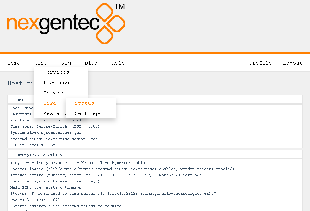

SDM service features and functionality are defined in different configuration files
Edid a config file using the web interface, for example sdm.conf
Do not edid a config file unless you are very sure what you do
Web interface default login
admin / nexgentec
Open a browser and enter the devices network address in the address bar, press enter
Navigate to SDM -> Files -> Config

Download the sdm.conf file
Make your changes to the sdm.conf file and save as unix format text file. configuration options
Upload the sdm.conf file, it will overwrite the existing one
Restart SDM process, Host -> Services -> Software Defined Matrix Service (this step is not needed for .toml files)
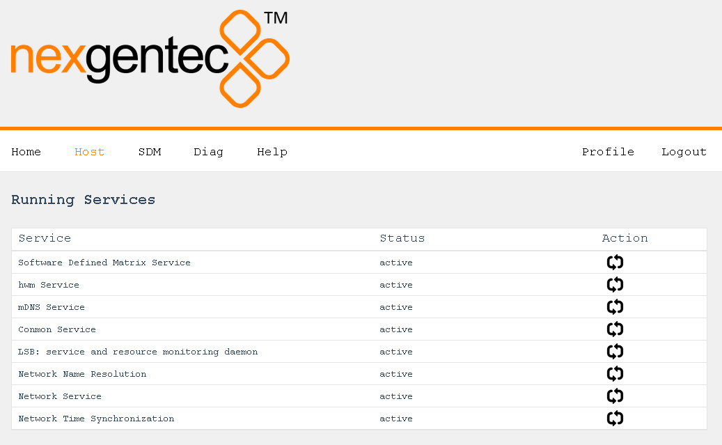
This section describes the various configuration options sdm.conf file can contain.
Use UNIX file fomatting when editing the file
File entries must be formatted as follows:
[Section]
key=value
For example to activate syslog:
[syslog]
address=“server.example.com”
port=53
level=6
tag=“sdm”
Do not delete the uuid, it identifies the sdm software. All licenses are bound to the uuid which is individual to every instance of sdm, it is like a product key for an OS
| Section | Key | Value | Example | Supported Versions |
|---|---|---|---|---|
| uuid | key | 408aca84-a2b0-11eb-bcbc-0242ac130002 | key=408aca84-a2b0-11eb-bcbc-0242ac130002 | >v0.0.1 |
| Section | Key | Value | Example | Supported Versions |
|---|---|---|---|---|
| logLevel | level | 1-7 | level=1 | >v0.0.1 |
| Section | Key | Value | Example | Supported Versions |
|---|---|---|---|---|
| syslog | level | 1-7 | level=6 | >v0.0.1 |
| address | your servers address | address=“server.example.com” | >v0.0.1 | |
| port | 53 or custom | port=53 | >v0.0.1 | |
| tag | sdm | tag=“sdm” | >v0.0.1 |
logAuth is for only internal usage
| Section | Key | Value | Example | Supported Versions |
|---|---|---|---|---|
| logAuth | key | key="" | >v0.0.1 |
| Section | Key | Value | Example | Supported Versions |
|---|---|---|---|---|
| api | jrpc2TCPInterface | Any network interface | jrpc2TCPInterface=“enp1s0” | >v1.8.50 |
| jrpc2TCPPort | Default: 64823 | jrpc2TCPPort=64823 | >v1.8.50 | |
| jrpc2HTTPInterface | Any network interface | jrpc2HTTPInterface=“enp1s0” | >v1.8.50 | |
| jrpc2HTTPPort | Default: 64880 | jrpc2HTTPPort=64880 | >v1.8.50 | |
| jrpc2Console | on/off | jrpc2Console=on | >v1.8.50 |
| Section | Key | Value | Example | Supported Versions |
|---|---|---|---|---|
| dante | primary | Any network interface | primary=“enp1s0” | >v1.8.50 |
| secondary | Any network interface | secondary=“enp2s0” | >v1.8.50 |
| Section | Key | Value | Example | Supported Versions |
|---|---|---|---|---|
| preset | recallPresetIDOnStart | Any preset as defined in presets_config.toml | recallOnStart=1 | >v1.8.50 |
| preset | recallPresetNameOnStart | Any preset as defined in presets_config.toml | recallOnStart=mypreset | >v1.8.50 |
| recallOnStartDelay | x (seconds) | recallOnStartDelay=10 | >v1.8.50 |
ifConfig is deprecated
Use api section to define interface/port for 3rd party communication and dante section to define the interfaces used for Dante™
| Section | Key | Value | Example | Supported Versions |
|---|---|---|---|---|
| dante | primary | Any network interface | primary=“enp1s0” | <v1.8.50 |
| secondary | Any network interface | secondary=“enp2s0” | <v1.8.50 | |
| cmdServer | Any network interface | cmdServer=“enp2s0” | <v1.8.50 |
cmdServer is deprecated
Use api section to define the port for 3rd party communication
| Section | Key | Value | Example | Supported Versions |
|---|---|---|---|---|
| cmdServer | port | port=48648 | <v1.8.50 |
Presets can be recalled on start up and using the Control API
Use UNIX file fomatting when editing the file
Generate yourself an example Generate example
See the fully commented definition below
[[preset]]

  # ID (s) of the preset object, mandatory
  preset_id = [56, 59, 33, 38]

  # Name of the preset object, can be omitted
  preset_name = "MyPreset_1"

  # Destination object
  [preset.destination]

    [[preset.destination.channel]]

      # Dante channel name, mandatory for Dante devices
      channel_name = "SDMS0000011"

      # Channel index, if omitted the order of the channels below the object determines the index
      index = 1

      # Dante device name, can be omitted but should not.
      node_name = "MyDanteDevice_1"

    [[preset.destination.channel]]

      # Dante channel name, mandatory for Dante devices
      channel_name = "SDMS0000012"

      # Channel index, if omitted the order of the channels below the object determines the index
      index = 2

      # Dante device name, can be omitted but should not.
      node_name = "MyDanteDevice_1"

    [[preset.destination.channel]]

      # Dante channel name, mandatory for Dante devices
      channel_name = "SDMS0000013"

      # Channel index, if omitted the order of the channels below the object determines the index
      index = 3

      # Dante device name, can be omitted but should not.
      node_name = "MyDanteDevice_1"

    [[preset.destination.channel]]

      # Dante channel name, mandatory for Dante devices
      channel_name = "SDMS0000014"

      # Channel index, if omitted the order of the channels below the object determines the index
      index = 4

      # Dante device name, can be omitted but should not.
      node_name = "MyDanteDevice_1"

  # Source object
  [preset.source]

    [[preset.source.channel]]

      # Dante channel name, mandatory for Dante devices
      channel_name = "SDMS0000011"

      # Channel index, if omitted the order of the channels below the object determines the index
      index = 1

      # Dante device name, can be omitted but should not.
      node_name = "MyDanteDevice_1"

    [[preset.source.channel]]

      # Dante channel name, mandatory for Dante devices
      channel_name = "SDMS0000012"

      # Channel index, if omitted the order of the channels below the object determines the index
      index = 2

      # Dante device name, can be omitted but should not.
      node_name = "MyDanteDevice_1"

    [[preset.source.channel]]

      # AES Flow name, mandatory for AES devices
      aes_flow_name = "239.69.x.x@MyAesDevice_1"

      # AES flow slot ID for this channel (1-x), mandatory for AES devices
      aes_flow_slot_id = 1

      # Channel index, if omitted the order of the channels below the object determines the index
      index = 3

    [[preset.source.channel]]

      # AES Flow name, mandatory for AES devices
      aes_flow_name = "239.69.x.x@MyAesDevice_1"

      # AES flow slot ID for this channel (1-x), mandatory for AES devices
      aes_flow_slot_id = 2

      # Channel index, if omitted the order of the channels below the object determines the index
      index = 4

[[preset]]

  preset_id = [26, 9, 3, 63]
  preset_name = "MyPreset_2"

  [preset.destination]

    [[preset.destination.channel]]
      channel_name = "SDMS0000021"
      index = 1
      node_name = "MyDanteDevice_2"

    [[preset.destination.channel]]
      channel_name = "SDMS0000022"
      index = 2
      node_name = "MyDanteDevice_2"

    [[preset.destination.channel]]
      channel_name = "SDMS0000023"
      index = 3
      node_name = "MyDanteDevice_2"

    [[preset.destination.channel]]
      channel_name = "SDMS0000024"
      index = 4
      node_name = "MyDanteDevice_2"

  [preset.source]

    [[preset.source.channel]]
      channel_name = "SDMS0000021"
      index = 1
      node_name = "MyDanteDevice_2"

    [[preset.source.channel]]
      channel_name = "SDMS0000022"
      index = 2
      node_name = "MyDanteDevice_2"

    [[preset.source.channel]]
      aes_flow_name = "239.69.x.x@MyAesDevice_2"
      aes_flow_slot_id = 1
      index = 3

    [[preset.source.channel]]
      aes_flow_name = "239.69.x.x@MyAesDevice_2"
      aes_flow_slot_id = 2
index = 4The source config file describe the sources which are selected by a Symetrix Symnet control number value. If there is no Symetrix device present or SDM should not listen to Symetrix this file can be omitted
Use UNIX file fomatting when editing the file
Generate yourself an example" Generate example
See the fully commented definition below
# Defaults can be omitted if all values are defined source specific.
# Source object defined values are taking precedence
[default]

  # Default delay settings for all objects that are not carrying its own settings for delay
  # Object defined values are taking precedence , can be omitted
  [default.delay]

    # Delay value (ms) on switch over, if omitted on object basis default settings apply
    switch = 500

[[source]]

  # Name of the source or destination object, can be omitted
  name = "MyDanteSource_1"

  [[source.channel]]

    # Dante channel name, mandatory for Dante devices
    channel_name = "SDMS0000011"

    # Channel index, if omitted the order of the channels below the object determines the index
    index = 1

    # Dante device name, can be omitted but should not.
    node_name = "MyDanteDevice_1"

  [[source.channel]]

    # Dante channel name, mandatory for Dante devices
    channel_name = "SDMS0000012"

    # Channel index, if omitted the order of the channels below the object determines the index
    index = 2

    # Dante device name, can be omitted but should not.
    node_name = "MyDanteDevice_1"

  # Object defined delay settings, if omitted on object basis default settings apply
  [source.delay]

    # Delay value (ms) on switch over, if omitted on object basis default settings apply
    switch = 800

  # Object defined Symetrix settings, mandatory
  [source.symnet]

    # Symetrix Control Number Value for this source object, mandatory
    control_value = 1

[[source]]

  # Name of the source or destination object, can be omitted
  name = "MyDanteSource_2"

  [[source.channel]]

    # Dante channel name, mandatory for Dante devices
    channel_name = "SDMS0000021"

    # Channel index, if omitted the order of the channels below the object determines the index
    index = 1

    # Dante device name, can be omitted but should not.
    node_name = "MyDanteDevice_2"

  [[source.channel]]

    # Dante channel name, mandatory for Dante devices
    channel_name = "SDMS0000022"

    # Channel index, if omitted the order of the channels below the object determines the index
    index = 2

    # Dante device name, can be omitted but should not.
    node_name = "MyDanteDevice_2"

  # Object defined delay settings, if omitted on object basis default settings apply
  [source.delay]

    # Delay value (ms) on switch over, if omitted on object basis default settings apply
    switch = 800

  # Object defined Symetrix settings, mandatory
  [source.symnet]

    # Symetrix Control Number Value for this source object, mandatory
    control_value = 2

[[source]]

  # Name of the source or destination object, can be omitted
  name = "MyDanteSource_3"

  [[source.channel]]

    # Dante channel name, mandatory for Dante devices
    channel_name = "SDMS0000031"

    # Channel index, if omitted the order of the channels below the object determines the index
    index = 1

    # Dante device name, can be omitted but should not.
    node_name = "MyDanteDevice_3"

  [[source.channel]]

    # Dante channel name, mandatory for Dante devices
    channel_name = "SDMS0000032"

    # Channel index, if omitted the order of the channels below the object determines the index
    index = 2

    # Dante device name, can be omitted but should not.
    node_name = "MyDanteDevice_3"

  # Object defined delay settings, if omitted on object basis default settings apply
  [source.delay]

    # Delay value (ms) on switch over, if omitted on object basis default settings apply
    switch = 800

  # Object defined Symetrix settings, mandatory
  [source.symnet]

    # Symetrix Control Number Value for this source object, mandatory
control_value = 3The destination config file describe the destinations which are identified by a Symetrix Symnet control number. If there is no Symetrix device present or SDM should not listen to Symetrix this file can be omitted
Use UNIX file fomatting when editing the file
Generate yourself an example Generate example
See the fully commented definition below
# Defaults can be omitted if all values are defined destination specific.
# Destination object defined values are taking precedence
[default]

  # Default delay settings for all objects that are not carrying its own settings for delay
  # Object defined values are taking precedence , can be omitted
  [default.delay]

    # Delay value (ms) on disconnect, if omitted on object basis default settings apply
    disconnect = 2000

  # Default Symetrix settings for all objects that are not carrying its own settings for delay
  # Object defined values are taking precedence, can be omitted
  [default.symnet]

    # Symetrix Site ID, defined in project settings, if omitted on object basis default settings apply
    site_id = 2

    # Symetrix DSP IP Address (v4), if omitted on object basis default settings apply
    unit_ip = "127.0.0.1"

[[destination]]

  # Name of the source or destination object, can be omitted
  name = "MyDanteDestination_1"

  [[destination.channel]]

    # Dante channel name, mandatory for Dante devices
    channel_name = "SDMD0000011"

    # Channel index, if omitted the order of the channels below the object determines the index
    index = 1

    # Dante device name, can be omitted but should not.
    node_name = "MyDanteDevice_1"

  [[destination.channel]]

    # Dante channel name, mandatory for Dante devices
    channel_name = "SDMD0000012"

    # Channel index, if omitted the order of the channels below the object determines the index
    index = 2

    # Dante device name, can be omitted but should not.
    node_name = "MyDanteDevice_1"

  # Object defined delay settings, if omitted on object basis default settings apply
  [destination.delay]

    # Delay value (ms) on disconnect, if omitted on object basis default settings apply
    disconnect = 800

  # Object defined Symetrix settings, mandatory
  [destination.symnet]

    # Symetrix Control Number for this destination object, mandatory
    control_id = 5001

    # Symetrix Control Number that is feed back to Symetrix once the destination has changed, can be omitted
    feedback_id = 6001

    # Symetrix Site ID, defined in project settings, if omitted on object basis default settings apply
    site_id = 3

    # Symetrix DSP IP Address (v4), if omitted on object basis default settings apply
    unit_ip = "127.0.0.2"

[[destination]]

  # Name of the source or destination object, can be omitted
  name = "MyDanteDestination_2"

  [[destination.channel]]

    # Dante channel name, mandatory for Dante devices
    channel_name = "SDMD0000021"

    # Channel index, if omitted the order of the channels below the object determines the index
    index = 1

    # Dante device name, can be omitted but should not.
    node_name = "MyDanteDevice_2"

  [[destination.channel]]

    # Dante channel name, mandatory for Dante devices
    channel_name = "SDMD0000022"

    # Channel index, if omitted the order of the channels below the object determines the index
    index = 2

    # Dante device name, can be omitted but should not.
    node_name = "MyDanteDevice_2"

  # Object defined delay settings, if omitted on object basis default settings apply
  [destination.delay]

    # Delay value (ms) on disconnect, if omitted on object basis default settings apply
    disconnect = 800

  # Object defined Symetrix settings, mandatory
  [destination.symnet]

    # Symetrix Control Number for this destination object, mandatory
    control_id = 5002

    # Symetrix Control Number that is feed back to Symetrix once the destination has changed, can be omitted
    feedback_id = 6002

    # Symetrix Site ID, defined in project settings, if omitted on object basis default settings apply
    site_id = 3

    # Symetrix DSP IP Address (v4), if omitted on object basis default settings apply
    unit_ip = "127.0.0.2"
Control sdm over TCP and HTTP using JSON-RPC 2.0
This section describes the communication protocol between the control system and SDM using RPC calls using the JSON-RPC 2.0 protocol
Commands must be formatted as defined in the JSON-RPC 2.0 protocol
All commands sent over TCP transport must end with <LF>
All replies are formatted as defined in the JSON-RPC 2.0 protocol
All replies over TCP transport end up with <LF>
<LF> stands for “line feed”, corresponding hex is 0x0A
JSON-RPC 2.0 commands can flow over different transport protocols, once enabled in the api section of the config files. Per default they might not be enabled. Edid the config file to suite your needs and restart sdm service
| Transport | Config | Datatype | Example | Supported Versions |
|---|---|---|---|---|
| TCP | jrpc2TCPInterface | string | enp1s0 | >v1.8.50 |
| TCP | jrpc2TCPPort | int | 64823 | >v1.8.50 |
| TCP | jrpc2HTTPInterface | string | enp1s0 | >v1.8.50 |
| TCP | jrpc2HTTPPort | int | 64880 | >v1.8.50 |
In subsequent pages all methods are described that can be used.
All JSON-RPC 2.0 services do support asynchronous message processing. 3rd party control Systems must keep tracking of the id’s to determine whether a request was successful or not
Any TCP capable application can be used to test commands. Do not forget to end up with <LF>
The body of the HTTP POST request must contain the complete JSON-RPC request message, encoded with Content-Type: application/json. Either a single request object or a list of request objects is supported. If the request completes, whether or not there is an error, the HTTP response is 200 (OK) for ordinary requests or 204 (No Response) for notifications, and the response body contains the JSON-RPC response. If the HTTP request method is not “POST”, SDM reports 405 (Method Not Allowed). If the Content-Type is not application/json, SDM reports 415 (Unsupported Media Type).
Test from a linux shell:
curl –header “Content-Type: application/json” –request POST –data ‘{“jsonrpc”:“2.0”,“id”:1,“method”:“sdm.Get”,“params”:{“property”:“version”}}’ http://host:64880
Get the running software version
| Method | Param | Value | Comment | Supported Versions |
|---|---|---|---|---|
| sdm.Get | property | version | Property name to get | >v1.8.50 |
{"jsonrpc":"2.0","id":1,"method":"sdm.Get","params":{"property":"version"}}| Result | Comment | |
|---|---|---|
| x.x.x | Version of sdm installed |
{"jsonrpc":"2.0","id":1,"result":"1.8.64"}Get the activation status
| Method | Param | Value | Comment | Supported Versions |
|---|---|---|---|---|
| sdm.Get | property | activation | Property name to get | >v1.8.50 |
{"jsonrpc":"2.0","id":1,"method":"sdm.Get","params":{"property":"activation"}}| Result | Key | Comment | Supported Versions |
|---|---|---|---|
| Trial | Deprecated >v1.8.70 | <v1.8.70 | |
| IsTrial | Is trial license is active? (deprecated >v1.8.70) | <v1.8.70 | |
| License | |||
| Channels | Allowed channels (unused)(deprecated >v1.8.70) | ||
| Devices | Allowed devices | ||
| Gracetime | Gracetime sdm runs with this license without online check | ||
| Exceed | Time exceed since last online license check | ||
| Valid | License if true, invalid if false | ||
| Expiration | Timestamp for fixed expiration licenses (defaults to 2000-01-01T00:00:00Z -> ignored) | >v1.8.72 | |
| Validation | Timestamp of last online validation | >v1.8.72 | |
| Refreshed | License online refreshed since last start. If false license infomation may be invalid |
{
	"jsonrpc": "2.0",
	"id": 1,
	"result": {
		"Trial": {
			"IsTrial": false
		},
		"License": {
			"Channels": 500,
			"Devices": 500,
			"Gracetime": 168,
			"Exceed": 0.002686415741388889,
			"Valid": true
			"Expiration":"2000-01-01T00:00:00Z"
			"Validation":"2021-09-10T16:47:08.452207569+02:00"
		},
		"Refreshed": true
	}
}Get the log level for sdm and associated processes
| Method | Param | Value | Comment | Supported Versions |
|---|---|---|---|---|
| system.Get | property | log.level | Property name to get | >v1.8.50 |
{"jsonrpc":"2.0","id":1,"method":"system.Get","params":{"property":"log.level"}}| Result | Comment | |
|---|---|---|
| x | Active log level |
{"jsonrpc":"2.0","id":1,"result":6}Set the log level for sdm and associated processes
| Method | Param | Value | Comment | Supported Versions |
|---|---|---|---|---|
| system.Set | property | log.level | Property name to set | >v1.8.50 |
| level | 0-7 | Log level to set | >v1.8.50 |
{"jsonrpc":"2.0","id":1,"method":"system.Set","params":{"property":"log.level","level":6}}| Result | Comment | |
|---|---|---|
| null | null means acknowledged, no error |
{"jsonrpc":"2.0","id":1,"result":null}Have sdm to create an example preset toml in the config directory. presets_config_example.toml will be created and can be modified and renamed as presets_config.toml. presets_config.toml is recognized by the system as file with preset definitions. See file content description for more info
| Method | Param | Value | Comment | Supported Versions |
|---|---|---|---|---|
| config.Create | file | presets_config_example.toml | Example file to create | >v1.8.67 |
{"jsonrpc":"2.0","id":1,"method":"config.Create","params":{"file":"presets_config_example.toml"}}| Result | Comment | |
|---|---|---|
| null | null means acknowledged, no error |
{"jsonrpc":"2.0","id":1,"result":null}Have sdm to create symnet source and destination config examples in the config directory. Either symnet_config_sources_example.toml or symnet_config_destinations_example.toml will be created and can be renamed as symnet_config_sources.toml, symnet_config_destinations.toml
symnet_config_sources.toml is recognized by the system as file with source definitions. See file content description for more info symnet_config_destinations.toml is recognized by the system as file with destination definitions. See file content description for more info
| Method | Param | Value | Comment | Supported Versions |
|---|---|---|---|---|
| config.Create | file | symnet_config_sources_example.toml | Example file to create | >v1.8.67 |
| symnet_config_destinations_example.toml | Example file to create | >v1.8.67 |
{"jsonrpc":"2.0","id":1,"method":"config.Create","params":{"file":"symnet_config_sources_example.toml"}}{"jsonrpc":"2.0","id":1,"method":"config.Create","params":{"file":"symnet_config_destinations_example.toml"}}| Result | Comment | |
|---|---|---|
| null | null means acknowledged, no error |
{"jsonrpc":"2.0","id":1,"result":null}Recall a preset defined in presets_config.toml. presets_config.toml is recognized by the system as file with preset definitions. See file content description for more info
| Method | Param | Value | Comment | Supported Versions |
|---|---|---|---|---|
| preset.Recall | preset | 1-x | Preset to recall | >v1.8.67 |
{"jsonrpc":"2.0","id":1,"method":"preset.Recall","params":{"preset":1}}| Result | Comment | |
|---|---|---|
| null | null means acknowledged, no error |
{"jsonrpc":"2.0","id":1,"result":null}Request a status from monitoring, like PTP states from Dante™
| Method | Param | Value | Comment | Supported Versions |
|---|---|---|---|---|
| monitor.Get | status | clocking | Status to get | >v1.8.50 |
{"jsonrpc":"2.0","id":1,"method":"monitor.Get", "params":{"status": "clocking"}}{
"jsonrpc": "2.0",
"id": 1,
"result": {
"SDM-DEV-DSP1-4": {
"Preferred": 0,
"Mutes": {},
"Ports": {
"1": {
"PortState": "PASSIVE",
"PathType": "MULTICAST",
"Layer": "LAYER3",
"LinkDown": 0,
"PtpVersion": 1,
"InterfaceIndex": 2
},
"2": {
"PortState": "SLAVE",
"PathType": "MULTICAST",
"Layer": "LAYER3",
"LinkDown": 0,
"PtpVersion": 2,
"InterfaceIndex": 2
},
"3": {
"PortState": "DISABLED",
"PathType": "UNICAST",
"Layer": "LAYER3",
"LinkDown": 0,
"PtpVersion": 1,
"InterfaceIndex": 2
},
"4": {
"PortState": "DISABLED",
"PathType": "UNICAST",
"Layer": "LAYER3",
"LinkDown": 0,
"PtpVersion": 2,
"InterfaceIndex": 2
}
}
},
"SDM-DEV-DSP2-1": {
"Preferred": 0,
"Mutes": {},
"Ports": {
"1": {
"PortState": "PASSIVE",
"PathType": "MULTICAST",
"Layer": "LAYER3",
"LinkDown": 0,
"PtpVersion": 1,
"InterfaceIndex": 2
},
"2": {
"PortState": "SLAVE",
"PathType": "MULTICAST",
"Layer": "LAYER3",
"LinkDown": 0,
"PtpVersion": 2,
"InterfaceIndex": 2
},
"3": {
"PortState": "DISABLED",
"PathType": "UNICAST",
"Layer": "LAYER3",
"LinkDown": 0,
"PtpVersion": 1,
"InterfaceIndex": 2
},
"4": {
"PortState": "DISABLED",
"PathType": "UNICAST",
"Layer": "LAYER3",
"LinkDown": 0,
"PtpVersion": 2,
"InterfaceIndex": 2
}
}
}
}
}Get all discovered Dante™ devices
| Method | Param | Value | Comment | Supported Versions |
|---|---|---|---|---|
| discovery.Get | type | media | Type for Dante™ is “media” | >v1.8.50 |
| domain | ADHOC | Dante domain, may be used in future versions |
{"jsonrpc":"2.0","id":1,"method":"discovery.Get","params":{"domain":"ADHOC","type":"media"}}| Result | Comment | |
|---|---|---|
| Map of all Dante devices discovered |
{"jsonrpc":"2.0","id":1,"result":["SDM-DEV-XIN1-3","SDM-DEV-DSP2-1","SDM-DEV-DSP1-4"]}Get all discovered sdp sending devices, mostly these are AES67 compatible devices
| Method | Param | Value | Comment | Supported Versions |
|---|---|---|---|---|
| discovery.Get | type | sdp | Type for AES67 is “sdp” | >v1.8.50 |
| domain | ADHOC | Dante domain, may be used in future versions |
{"jsonrpc":"2.0","id":1,"method":"discovery.Get","params":{"domain":"ADHOC","type":"sdp"}}| Result | Comment | |
|---|---|---|
| Map of all Dante AES67 flows announced |
{"jsonrpc":"2.0","id":1,"result":["239.69.40.217@SDM-Test","239.69.40.179@SDM-Foo"]}This section describes the communication protocol between the control system and SDM
Get all supported RCP methods
| Method | Param | Value | Comment | Supported Versions |
|---|---|---|---|---|
| rpc.serverInfo | >v1.8.50 |
{"jsonrpc":"2.0","id":1,"method":"rpc.serverInfo"}| Result | Key | Comment |
|---|---|---|
| methods | All supported methods that can be used by a 3rd party control system | |
| counters | Server counters | |
| startTime | Server start time |
{
	"jsonrpc": "2.0",
	"id": 1,
	"result": {
		"methods": ["config.Create", "discovery.Get", "monitor.Get", "preset.Recall", "routing.Create", "routing.Delete", "routing.Get", "routing.Subscribe", "sdm.Get", "system.Get", "system.Set"],
		"usesContext": false,
		"counters": {
			"rpc.bytesRead": 50,
			"rpc.requests": 1
		},
		"maxValue": {
			"rpc.bytesRead": 50
		},
		"startTime": "2021-04-22T06:19:41.709283225Z"
	}
}Get all received channels from a Dante™ device
| Method | Param | Value | Comment | Supported Versions |
|---|---|---|---|---|
| routing.Get | name | string | Name of the device | >v1.8.50 |
| component | rxchannels | >v1.8.50 | ||
| domain | ADHOC | Dante domain, may be used in future versions |
{"jsonrpc":"2.0","id":2,"method":"routing.Get","params":{"name":"SDM-DEV-DSP1-4","domain":"ADHOC","component":"rxchannels"}}| Result | Key | Comment |
|---|---|---|
| channels (map) | Receiving channels 1-x | |
| canonicalName | Channel canonical name | |
| label | Channel label name | |
| subscriptedLabel | Channel label from channel that is received | |
| subscriptedDevice | Device name from which the channel is received | |
| Name | Device name |
{
	"jsonrpc": "2.0",
	"id": 2,
	"result": {
		"channels": {
			"1": {
				"canonicalName": "Zone_Channels-Ch1",
				"label": "Zone_Channels-Ch1",
				"subscriptedLabel": "NONE",
				"subscriptedDevice": "NONE"
			},
			"21": {
				"canonicalName": "Zone_Channels-Ch21",
				"label": "Zone_Channels-Ch21",
				"subscriptedLabel": "Source_Channels-Ch45",
				"subscriptedDevice": "SDM-DEV-DSP1-4"
			}
		},
		"Name": "SDM-DEV-DSP1-4"
	}
}Get all sent channels from a Dante™ device
| Method | Param | Value | Comment | Supported Versions |
|---|---|---|---|---|
| routing.Get | name | string | Name of the device | >v1.8.50 |
| component | txchannels | >v1.8.50 | ||
| domain | ADHOC | Dante domain, may be used in future versions |
{"jsonrpc": "2.0","id":2,"method": "routing.Get","params":{"name":"SDM-DEV-DSP1-4","domain":"ADHOC","component":"txchannels"}}| Result | Key | Comment |
|---|---|---|
| channels (map) | Transmitting channels 1-x | |
| canonicalName | Channel canonical name | |
| labels | Channel labels (map) | |
| Name | Device name |
{
	"jsonrpc": "2.0",
	"id": 2,
	"result": {
		"channels": {
			"1": {
				"canonicalName": "01",
				"labels": {
					"0": "Source_Channels-Ch1"
				}
			},
			"10": {
				"canonicalName": "10",
				"labels": {
					"0": "Source_Channels-Ch10"
				}
			}
		},
		"Name": "SDM-DEV-DSP1-4"
	}
}Get all sent flows from a Dante™ device
| Method | Param | Value | Comment | Supported Versions |
|---|---|---|---|---|
| routing.Get | name | string | Name of the device | >v1.8.50 |
| component | txflows | >v1.8.50 | ||
| domain | ADHOC | Dante domain, may be used in future versions |
{"jsonrpc": "2.0","id":2,"method": "routing.Get","params":{"name":"SDM-DEV-DSP1-4","domain":"ADHOC","component":"txflows"}}| Result | Key | Sub | Comment |
|---|---|---|---|
| flows (map) | Transmitting flows 1-x | ||
| name | Flow name | ||
| Slots | Flow slots (map) | ||
| ChannelName | Name of the channel | ||
| ChannelID | Channel ID | ||
| ID | Flow ID | ||
| Interfaces | How many interfaces are used for this flow | ||
| Addresses | Flow Addresses (map) | ||
| Addr | Multicast IP Address | ||
| Port | Port | ||
| FlowClass | 1=Dante&trade, 2,3=AES67, 4=RTP | ||
| Aes67OrigAddress | AES67 original address if AES67 | ||
| Transport | AES67 or Dante | ||
| DestDevice | Destination device the flow flows to if unicast | ||
| Flow ID | Destination flow name on the device the flow flows to if unicast | ||
| Name | Device name |
{
	"jsonrpc": "2.0",
	"id": 2,
	"result": {
		"flows": {
			"0": {
				"name": "Source_Channels",
				"indexes": null,
				"Slots": {
					"0": {
						"ChannelName": "Source_Channels-Ch1",
						"ChannelID": 1
					},
					"1": {
						"ChannelName": "Source_Channels-Ch2",
						"ChannelID": 2
					}
				},
				"ID": 1,
				"Interfaces": 1,
				"Addresses": {
					"0": {
						"Addr": "239.255.105.118",
						"Port": 4321
					}
				},
				"FlowClass": 1,
				"Aes67OrigAddress": "",
				"Transport": "DANTE",
				"DestDevice": "",
				"DestFlow": ""
			}

		},
		"Name": "SDM-DEV-DSP1-4"
	}
}Get all received flows from a Dante™ device
| Method | Param | Value | Comment | Supported Versions |
|---|---|---|---|---|
| routing.Get | name | string | Name of the device | >v1.8.50 |
| component | rxflows | >v1.8.50 | ||
| domain | ADHOC | Dante domain, may be used in future versions |
{"jsonrpc": "2.0","id": 2,"method": "routing.Get","params":{"name":"SDM-DEV-DSP1-4","domain": "ADHOC","component":"rxflows"}}| Result | Key | Sub | Comment |
|---|---|---|---|
| flows (map) | Transmitting flows 1-x | ||
| name | Flow name | ||
| Slots | Flow slots (map) | ||
| Channels (map) | Map of the channels received in this flow slot | ||
| ID | Flow ID | ||
| Interfaces | How many interfaces are used for this flow | ||
| Addresses | Flow Addresses (map) | ||
| Addr | Multicast IP Address | ||
| Port | Port | ||
| FlowClass | 1=Dante&trade, 2,3=AES67, 4=RTP | ||
| Aes67OrigAddress | AES67 original address if AES67 | ||
| Transport | AES67 or Dante | ||
| Name | Device name |
{
	"jsonrpc": "2.0",
	"id": 2,
	"result": {
		"flows": {
			"0": {
				"name": "",
				"Slots": {
					"0": {
						"Channels": {
							"0": "Zone_Channels-Ch51"
						}
					},
					"1": {
						"Channels": {
							"0": "Zone_Channels-Ch52"
						}
					}
				},
				"ID": 1,
				"Interfaces": 1,
				"Addresses": {
					"0": {
						"Addr": "239.69.40.217",
						"Port": 5004
					}
				},
				"FlowClass": 1,
				"Aes67OrigAddress": "",
				"Transport": "Dante"
			},

			"2": {
				"name": "",
				"Slots": {
					"0": {
						"Channels": {
							"0": "Zone_Channels-Ch1"
						}
					},
					"1": {
						"Channels": {
							"0": "Zone_Channels-Ch2"
						}
					}
				},
				"ID": 3,
				"Interfaces": 1,
				"Addresses": {
					"0": {
						"Addr": "239.69.2.156",
						"Port": 5004
					}
				},
				"FlowClass": 2,
				"Aes67OrigAddress": "239.69.2.156",
				"Transport": "AES67"
			}
		},
		"Name": "SDM-DEV-DSP1-4"
	}
}Create a new routing from a Dante™ or AES67 device to a a Dante™ device
| Method | Param | Sub-table key | Comment | Supported Versions | |
|---|---|---|---|---|---|
| routing.Create | tx | channelName | Source channel label/name/canonical name | >v1.8.50 | |
| nodeName | Source node name | >v1.8.50 | |||
| aesFlowName | Source flow name | >v1.8.67 | |||
| aesFlowSlotID | Slot ID of flow | >v1.8.67 | |||
| rx | destination | Destination channel label/name/canonical name | >v1.8.50 | ||
| nodeName | Destination node name | >v1.8.50 |
Include node name to create a new routing
Even if it is allowed to create a new routing only based on the channel name, it is better to include the device name. The changeover is done more quickly
{
   "jsonrpc":"2.0",
   "id":1,
   "method":"routing.Create",
   "params":[
      {
         "rx":{
            "channelName":"Zone_Channels-Ch10"
         },
         "tx":{
            "channelName":"Source_Channels-Ch10"
         }
      }
   ]
}{
"jsonrpc":"2.0",
"id":1,
"method":"routing.Create",
"params":[
{
"rx":{
"nodeName":"SDM-DEV-DSP1-4",
"channelName":"Zone_Channels-Ch10"
},
"tx":{
"nodeName":"SDM-DEV-DSP1-4",
"channelName":"Source_Channels-Ch10"
}
}
]
}{
"jsonrpc":"2.0",
"id":1,
"method":"routing.Create",
"params":[
{
"tx":{
"nodeName":"",
"channelName":"Zone_Channels-Ch10"
},
"tx":{
"aesFlowName":"239.69.40.217@Test-BTI",
"aesFlowSlotID":1
}
},
{
"rx":{
"nodeName":"",
"channelName":"Zone_Channels-Ch11"
},
"rx":{
"aesFlowName":"239.69.40.217@Test-BTI",
"aesFlowSlotID":2
}
}
]
}| Result | ||
|---|---|---|
| null | null means acknowledged, no error |
{"jsonrpc":"2.0","id":1,"result":null}Delete a routing from a Dante™ or AES67 device to a a Dante™ device
| Method | Param | Sub-table key | Comment | Supported Versions | |
|---|---|---|---|---|---|
| routing.Delete | rx | Destination | Destination channel label/name/canonical name | >v1.8.50 | |
| nodeName | Destination node name | >v1.8.50 |
Include node name to delete routing
Even if it is allowed to delete a routing only based on the channel name, it is better to include the device name. The disconnect is done more quickly
{
   "jsonrpc":"2.0",
   "id":1,
   "method":"routing.Delete",
   "params":[
      {
         "RX":{
            "ChannelName":"Zone_Channels-Ch11"
         }
      }
   ]
}{
"jsonrpc":"2.0",
"id":1,
"method":"routing.Delete",
"params":[
{
"RX":{
"NodeName":"SDM-DEV-DSP1-4",
"ChannelName":"Zone_Channels-Ch11"
}
}
]
}| Result | ||
|---|---|---|
| null | null means acknowledged, no error |
{"jsonrpc": "2.0","id": 1,"result": null}SDM can help you diagnose several shortcomings in the network
Dante™ networks do need a correctly set IGMP Querier
The status of a IGMP Querier can be sniffed on the page Diag > IGMP QUerier
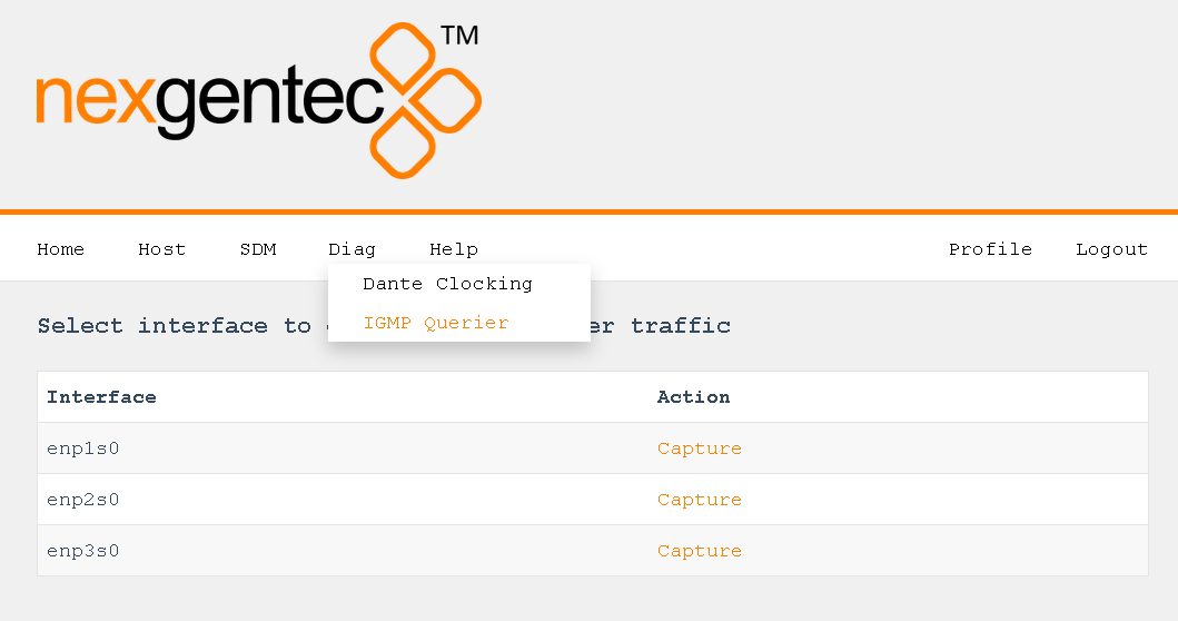
Once you selected the Interface capture begins
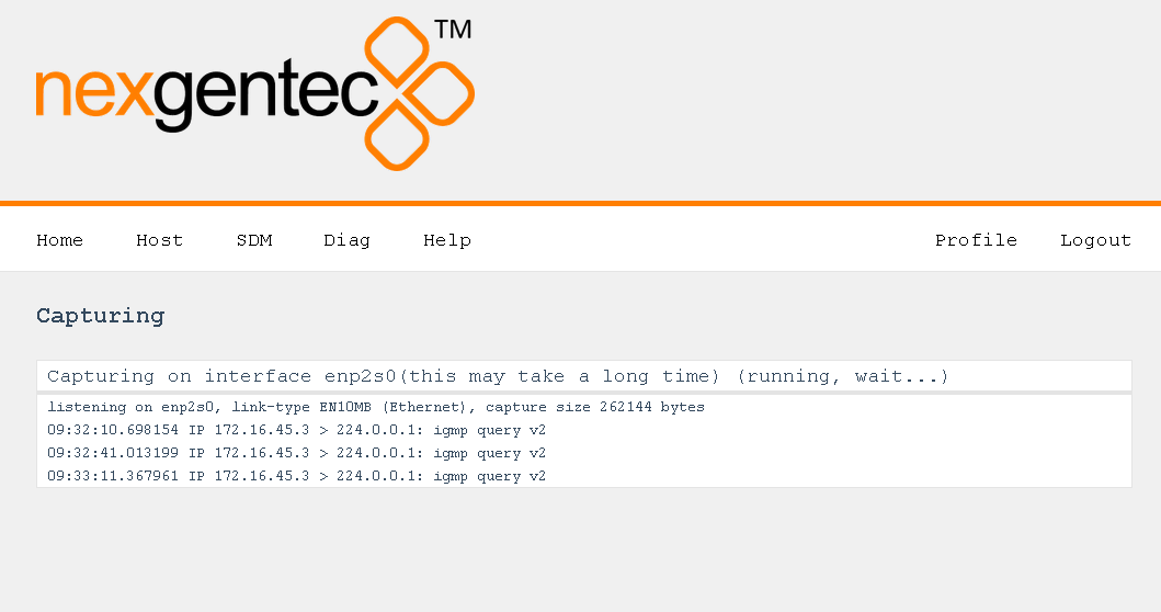
Dante™ networks use PTP for time synchronization.
The clocking status of all dante devices can be sniffed on the page Diag > Dante Clocking
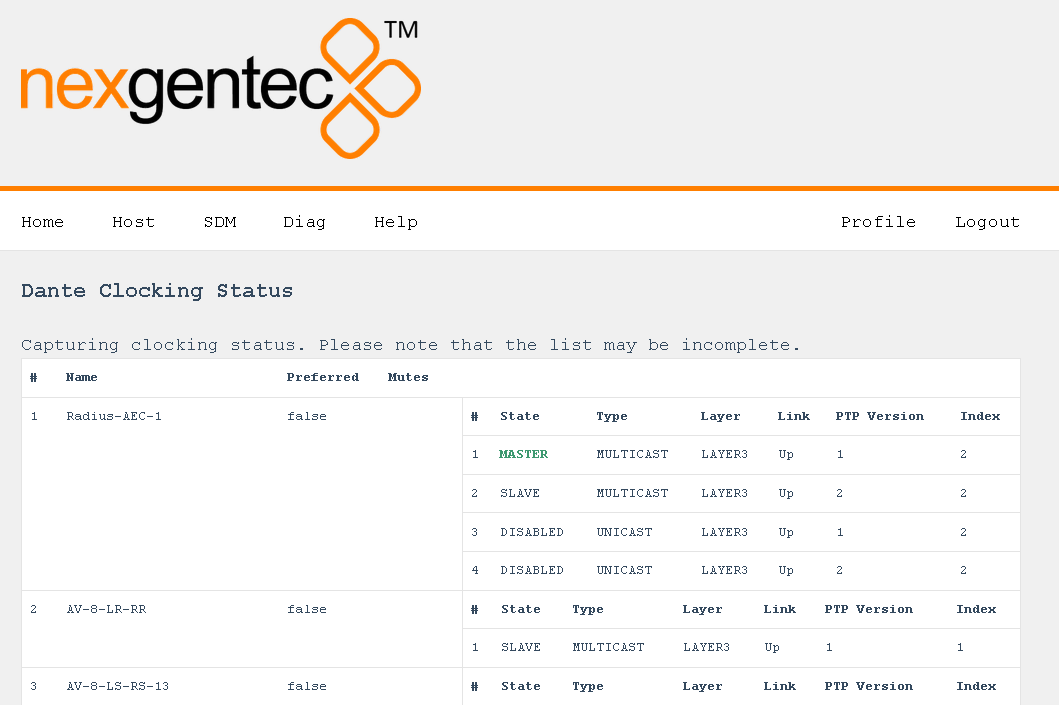
Every SDM needs a valid license to work. SDM confirms validity online at least every 7 days
The status of the license can be viewed on the status page SDM > license
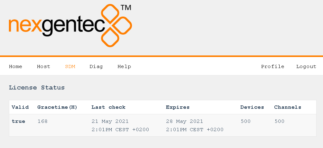
A detailed explanation of the reported fields can be here
Updates can be uploaded and activated under Help > Update
Once online updates are activated SDM checks for updates for SDM and associated services, as well as for operating system updates
Nothing to see here yet
Welcome to the Firmware section!
If you are not redirected automatically, click here.
| Connector | |
|---|---|
| Ethernet | |
| Net 1 | Gigabit Ethernet (Intel i210AT) |
| Net 2 | Gigabit Ethernet (Intel i210AT) |
| Net 3 | Gigabit Ethernet (Intel i210AT) |
| Serial | |
| DB9 serial | Deactivated |
| Power | |
| Jack (2.5 mm) center positive | 12V DC, about 6 to 12W |
| Power | 12V, 12W max |
| Heat Dissipation | Max 42 BTU / HR |
| Operating temp | 0°C – 60°C |
| Dimensions | L: 238mm, W: 208mm, H:44mm |
| Compliance | CE, ROHS |
| Weight | 900g |
None of the specified protocols or ports, nor the communication can be changed. (except port configurable in sdm.config )
Its wise to review the lists and allow SDM to communicate with all ports and protocols defined.
SDM will not work without any of the ports and protocols defined.
SDM need frequent internet access Details
Depending on the configuration physical ports, VLAN or bridges used for Dante™ may use these ports for communication.
| Address | Port | Usage | Type |
|---|---|---|---|
| 239.255.0.0/16 | 4321 | ATP Multicast Audio | Multicast |
| 239.69.0.0/16 | 5004 | AES67 Multicast Audio (RTP / AVP port) | Multicast |
| 224.0.1.129-132 | 319, 320 | PTP | Multicast & Unicast when using DDM |
| 224.0.0.251 | 5353 | mDNS | Multicast |
| 224.0.0.230 – 233 | 8700 – 8708 | Multicast Control and Monitoring | Multicast |
| 239.254.1.1 | 9998 | Logging | Multicast |
| 239.254.3.3 | 9998 | PTP Logging (if enabled) | Multicast |
| 239.254.44.44 | 9998 | Logging | Multicast |
| 239.255.255.255 | 9875 | SAP (AES67 discovery) | Multicast |
| UDP | 28800, 28700-28708 | Via control & monitoring | Unicast |
| UDP | 38800, 38700-38708 | DVS control & monitoring | Unicast |
| UDP | 14336 -14591 | Unicast Audio [Excluding Via] | Unicast |
| UDP | 34336-34600 | Unicast Audio [Via Only] | Unicast |
| UDP | 4440, 4444, 4455 | Audio Control [Excluding Via] | Unicast |
| UDP | 24440, 24441,24444,24455 | Audio Control | Unicast |
| UDP | 4777 | Via Control | Unicast |
| TCP | 4777 | Via Websocket | Unicast |
| UDP | 8850,28900, 24445 | Via control & Monitoring | Unicast |
| UDP | 8850,38900,8899 | DVS control & monitoring | Unicast |
| UDP | 8000 | Dante Domain Manager Device Port | Unicast |
| UDP | 8001 | Dante Millau Device Proxy | Unicast |
| UDP | 8002 | Dante Lock Server | Unicast |
| UDP | 8751 | Dante Controller metering port | Unicast |
| UDP | 8800 | Control & Monitoring | Unicast |
| TCP | 8753 | mDNS clients | Unicast |
| TCP | 16100-16131 | HDCP Authentication for Video Endpoints | Unicast |
| UDP | 61440-61951 | FPGA level audio flow keepalive | Unicast |
Depending on the configuration physical ports, VLAN or bridges used for control may use these ports for communication.
| Protocol | Source IP | Source Port | Destination IP | Destination Port | Description |
|---|---|---|---|---|---|
| HTTP | All | all | Control interface Address | Port configured in sdm.config | Control over HTTP |
| TCP | All | all | Control interface Address | Port configured in sdm.config | Control over TCP |
| Protocol | Source IP | Source Port | Destination | Destination Port | Description |
|---|---|---|---|---|---|
| TCP | All interfaces | all | l02.genesis-technologies.ch | 443 | nexgentec™ license service |
| UDP | All interfaces | all | swan.genesis-technologies.ch | 443 | nexgentec™ maintenance service |
| TCP | All interfaces | all | DNS service | 53 | DNS |
| UDP | All interfaces | all | DNS service | 53 | DNS |
| UDP | All interfaces | all | NTP service | 123 | NTP |
| TCP | All interfaces | all | www.app.qbee.io | 443 | 3rd party maintenance service |
At least every 7 days a successful license check must be possible. If not SDM stops working
Send the SDM device back to where you bought it. We have no intention to change our mind.
Sure we listen, just give us a call.
Several user settings can be made on the Profile page.
To protect the access to the web interface another password can be set
Do not lose the password nexgentec customer support must be contacted to reset the password.
The time format for the web interface
SDM and associated software may use 3rd party code with their given copyrights. For compliance reasons we are required list them here.
Copyright (c) 2017, Michael J. Fromberger
All rights reserved.

Redistribution and use in source and binary forms, with or without
modification, are permitted provided that the following conditions are met:

1. Redistributions of source code must retain the above copyright notice, this
   list of conditions and the following disclaimer.

2. Redistributions in binary form must reproduce the above copyright notice,
   this list of conditions and the following disclaimer in the documentation
   and/or other materials provided with the distribution.

3. Neither the name of the copyright holder nor the names of its contributors
   may be used to endorse or promote products derived from this software
   without specific prior written permission.

THIS SOFTWARE IS PROVIDED BY THE COPYRIGHT HOLDERS AND CONTRIBUTORS "AS IS" AND
ANY EXPRESS OR IMPLIED WARRANTIES, INCLUDING, BUT NOT LIMITED TO, THE IMPLIED
WARRANTIES OF MERCHANTABILITY AND FITNESS FOR A PARTICULAR PURPOSE ARE
DISCLAIMED. IN NO EVENT SHALL THE COPYRIGHT HOLDER OR CONTRIBUTORS BE LIABLE
FOR ANY DIRECT, INDIRECT, INCIDENTAL, SPECIAL, EXEMPLARY, OR CONSEQUENTIAL
DAMAGES (INCLUDING, BUT NOT LIMITED TO, PROCUREMENT OF SUBSTITUTE GOODS OR
SERVICES; LOSS OF USE, DATA, OR PROFITS; OR BUSINESS INTERRUPTION) HOWEVER
CAUSED AND ON ANY THEORY OF LIABILITY, WHETHER IN CONTRACT, STRICT LIABILITY,
OR TORT (INCLUDING NEGLIGENCE OR OTHERWISE) ARISING IN ANY WAY OUT OF THE USE
OF THIS SOFTWARE, EVEN IF ADVISED OF THE POSSIBILITY OF SUCH DAMAGE.The MIT License (MIT)
Copyright (C) 2012 termbox-go authors
Copyright (c) 2015 Emanuele Iannone
Permission is hereby granted, free of charge, to any person obtaining a copy
of this software and associated documentation files (the "Software"), to deal
in the Software without restriction, including without limitation the rights
to use, copy, modify, merge, publish, distribute, sublicense, and/or sell
copies of the Software, and to permit persons to whom the Software is
furnished to do so, subject to the following conditions:
The above copyright notice and this permission notice shall be included in all
copies or substantial portions of the Software.
THE SOFTWARE IS PROVIDED "AS IS", WITHOUT WARRANTY OF ANY KIND, EXPRESS OR
IMPLIED, INCLUDING BUT NOT LIMITED TO THE WARRANTIES OF MERCHANTABILITY,
FITNESS FOR A PARTICULAR PURPOSE AND NONINFRINGEMENT. IN NO EVENT SHALL THE
AUTHORS OR COPYRIGHT HOLDERS BE LIABLE FOR ANY CLAIM, DAMAGES OR OTHER
LIABILITY, WHETHER IN AN ACTION OF CONTRACT, TORT OR OTHERWISE, ARISING FROM,
OUT OF OR IN CONNECTION WITH THE SOFTWARE OR THE USE OR OTHER DEALINGS IN THE
SOFTWARE.Copyright (c) 2012 The Go Authors. All rights reserved.
Copyright (c) 2012-2019 fsnotify Authors. All rights reserved.
Redistribution and use in source and binary forms, with or without
modification, are permitted provided that the following conditions are
met:
* Redistributions of source code must retain the above copyright
notice, this list of conditions and the following disclaimer.
* Redistributions in binary form must reproduce the above
copyright notice, this list of conditions and the following disclaimer
in the documentation and/or other materials provided with the
distribution.
* Neither the name of Google Inc. nor the names of its
contributors may be used to endorse or promote products derived from
this software without specific prior written permission.
THIS SOFTWARE IS PROVIDED BY THE COPYRIGHT HOLDERS AND CONTRIBUTORS
"AS IS" AND ANY EXPRESS OR IMPLIED WARRANTIES, INCLUDING, BUT NOT
LIMITED TO, THE IMPLIED WARRANTIES OF MERCHANTABILITY AND FITNESS FOR
A PARTICULAR PURPOSE ARE DISCLAIMED. IN NO EVENT SHALL THE COPYRIGHT
OWNER OR CONTRIBUTORS BE LIABLE FOR ANY DIRECT, INDIRECT, INCIDENTAL,
SPECIAL, EXEMPLARY, OR CONSEQUENTIAL DAMAGES (INCLUDING, BUT NOT
LIMITED TO, PROCUREMENT OF SUBSTITUTE GOODS OR SERVICES; LOSS OF USE,
DATA, OR PROFITS; OR BUSINESS INTERRUPTION) HOWEVER CAUSED AND ON ANY
THEORY OF LIABILITY, WHETHER IN CONTRACT, STRICT LIABILITY, OR TORT
(INCLUDING NEGLIGENCE OR OTHERWISE) ARISING IN ANY WAY OUT OF THE USE
OF THIS SOFTWARE, EVEN IF ADVISED OF THE POSSIBILITY OF SUCH DAMAGE.Copyright (c) 2009,2014 Google Inc. All rights reserved.
Redistribution and use in source and binary forms, with or without
modification, are permitted provided that the following conditions are
met:
* Redistributions of source code must retain the above copyright
notice, this list of conditions and the following disclaimer.
* Redistributions in binary form must reproduce the above
copyright notice, this list of conditions and the following disclaimer
in the documentation and/or other materials provided with the
distribution.
* Neither the name of Google Inc. nor the names of its
contributors may be used to endorse or promote products derived from
this software without specific prior written permission.
THIS SOFTWARE IS PROVIDED BY THE COPYRIGHT HOLDERS AND CONTRIBUTORS
"AS IS" AND ANY EXPRESS OR IMPLIED WARRANTIES, INCLUDING, BUT NOT
LIMITED TO, THE IMPLIED WARRANTIES OF MERCHANTABILITY AND FITNESS FOR
A PARTICULAR PURPOSE ARE DISCLAIMED. IN NO EVENT SHALL THE COPYRIGHT
OWNER OR CONTRIBUTORS BE LIABLE FOR ANY DIRECT, INDIRECT, INCIDENTAL,
SPECIAL, EXEMPLARY, OR CONSEQUENTIAL DAMAGES (INCLUDING, BUT NOT
LIMITED TO, PROCUREMENT OF SUBSTITUTE GOODS OR SERVICES; LOSS OF USE,
DATA, OR PROFITS; OR BUSINESS INTERRUPTION) HOWEVER CAUSED AND ON ANY
THEORY OF LIABILITY, WHETHER IN CONTRACT, STRICT LIABILITY, OR TORT
(INCLUDING NEGLIGENCE OR OTHERWISE) ARISING IN ANY WAY OUT OF THE USE
OF THIS SOFTWARE, EVEN IF ADVISED OF THE POSSIBILITY OF SUCH DAMAGE.MIT License
Copyright (c) 2017 David 大伟
Permission is hereby granted, free of charge, to any person obtaining a copy
of this software and associated documentation files (the "Software"), to deal
in the Software without restriction, including without limitation the rights
to use, copy, modify, merge, publish, distribute, sublicense, and/or sell
copies of the Software, and to permit persons to whom the Software is
furnished to do so, subject to the following conditions:
The above copyright notice and this permission notice shall be included in all
copies or substantial portions of the Software.
THE SOFTWARE IS PROVIDED "AS IS", WITHOUT WARRANTY OF ANY KIND, EXPRESS OR
IMPLIED, INCLUDING BUT NOT LIMITED TO THE WARRANTIES OF MERCHANTABILITY,
FITNESS FOR A PARTICULAR PURPOSE AND NONINFRINGEMENT. IN NO EVENT SHALL THE
AUTHORS OR COPYRIGHT HOLDERS BE LIABLE FOR ANY CLAIM, DAMAGES OR OTHER
LIABILITY, WHETHER IN AN ACTION OF CONTRACT, TORT OR OTHERWISE, ARISING FROM,
OUT OF OR IN CONNECTION WITH THE SOFTWARE OR THE USE OR OTHER DEALINGS IN THE
SOFTWARE.Copyright (c) 2009 The Go Authors. All rights reserved.
Redistribution and use in source and binary forms, with or without
modification, are permitted provided that the following conditions are
met:
* Redistributions of source code must retain the above copyright
notice, this list of conditions and the following disclaimer.
* Redistributions in binary form must reproduce the above
copyright notice, this list of conditions and the following disclaimer
in the documentation and/or other materials provided with the
distribution.
* Neither the name of Google Inc. nor the names of its
contributors may be used to endorse or promote products derived from
this software without specific prior written permission.
THIS SOFTWARE IS PROVIDED BY THE COPYRIGHT HOLDERS AND CONTRIBUTORS
"AS IS" AND ANY EXPRESS OR IMPLIED WARRANTIES, INCLUDING, BUT NOT
LIMITED TO, THE IMPLIED WARRANTIES OF MERCHANTABILITY AND FITNESS FOR
A PARTICULAR PURPOSE ARE DISCLAIMED. IN NO EVENT SHALL THE COPYRIGHT
OWNER OR CONTRIBUTORS BE LIABLE FOR ANY DIRECT, INDIRECT, INCIDENTAL,
SPECIAL, EXEMPLARY, OR CONSEQUENTIAL DAMAGES (INCLUDING, BUT NOT
LIMITED TO, PROCUREMENT OF SUBSTITUTE GOODS OR SERVICES; LOSS OF USE,
DATA, OR PROFITS; OR BUSINESS INTERRUPTION) HOWEVER CAUSED AND ON ANY
THEORY OF LIABILITY, WHETHER IN CONTRACT, STRICT LIABILITY, OR TORT
(INCLUDING NEGLIGENCE OR OTHERWISE) ARISING IN ANY WAY OUT OF THE USE
OF THIS SOFTWARE, EVEN IF ADVISED OF THE POSSIBILITY OF SUCH DAMAGE.Copyright (c) 2012 Péter Surányi. Portions Copyright (c) 2009 The Go
Authors. All rights reserved.
Redistribution and use in source and binary forms, with or without
modification, are permitted provided that the following conditions are
met:
* Redistributions of source code must retain the above copyright
notice, this list of conditions and the following disclaimer.
* Redistributions in binary form must reproduce the above
copyright notice, this list of conditions and the following disclaimer
in the documentation and/or other materials provided with the
distribution.
* Neither the name of Google Inc. nor the names of its
contributors may be used to endorse or promote products derived from
this software without specific prior written permission.
THIS SOFTWARE IS PROVIDED BY THE COPYRIGHT HOLDERS AND CONTRIBUTORS
"AS IS" AND ANY EXPRESS OR IMPLIED WARRANTIES, INCLUDING, BUT NOT
LIMITED TO, THE IMPLIED WARRANTIES OF MERCHANTABILITY AND FITNESS FOR
A PARTICULAR PURPOSE ARE DISCLAIMED. IN NO EVENT SHALL THE COPYRIGHT
OWNER OR CONTRIBUTORS BE LIABLE FOR ANY DIRECT, INDIRECT, INCIDENTAL,
SPECIAL, EXEMPLARY, OR CONSEQUENTIAL DAMAGES (INCLUDING, BUT NOT
LIMITED TO, PROCUREMENT OF SUBSTITUTE GOODS OR SERVICES; LOSS OF USE,
DATA, OR PROFITS; OR BUSINESS INTERRUPTION) HOWEVER CAUSED AND ON ANY
THEORY OF LIABILITY, WHETHER IN CONTRACT, STRICT LIABILITY, OR TORT
(INCLUDING NEGLIGENCE OR OTHERWISE) ARISING IN ANY WAY OUT OF THE USE
OF THIS SOFTWARE, EVEN IF ADVISED OF THE POSSIBILITY OF SUCH DAMAGE.The MIT License (MIT)
Copyright (c) 2014 Nate Finch
Permission is hereby granted, free of charge, to any person obtaining a copy
of this software and associated documentation files (the "Software"), to deal
in the Software without restriction, including without limitation the rights
to use, copy, modify, merge, publish, distribute, sublicense, and/or sell
copies of the Software, and to permit persons to whom the Software is
furnished to do so, subject to the following conditions:
The above copyright notice and this permission notice shall be included in all
copies or substantial portions of the Software.
THE SOFTWARE IS PROVIDED "AS IS", WITHOUT WARRANTY OF ANY KIND, EXPRESS OR
IMPLIED, INCLUDING BUT NOT LIMITED TO THE WARRANTIES OF MERCHANTABILITY,
FITNESS FOR A PARTICULAR PURPOSE AND NONINFRINGEMENT. IN NO EVENT SHALL THE
AUTHORS OR COPYRIGHT HOLDERS BE LIABLE FOR ANY CLAIM, DAMAGES OR OTHER
LIABILITY, WHETHER IN AN ACTION OF CONTRACT, TORT OR OTHERWISE, ARISING FROM,
OUT OF OR IN CONNECTION WITH THE SOFTWARE OR THE USE OR OTHER DEALINGS IN THE
SOFTWARE.