Network
This guide applies to all units running ngtOS >= version 1.0.13 (beta-rc3)
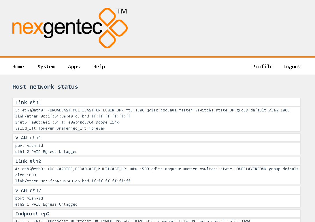
Status
The status of the network connections can be viewed on the status page System > Network > Status
General
Points to consider:
- Never assign a gateway to more than one connection.
- Never place more than one connection in the same IP address range.
- Use DNS servers that are reachable.
- Avoid leaving two interfaces connected to the network on DHCP.
- The unit requires internet access. This is necessary in case service personnel need to access the unit using the built-in support tool.
If things go wrong:
- Try to locate the device using your DHCP server. Attempt this on all available Ethernet interfaces.
- The display on the unit shows the full configuration for each interface, including the path to access the IP address.
Basic Functionality
In general, the physical network interfaces and the internal endpoints should be understood as a managed switch infrastructure. Each physical port can take untagged and tagged VLANs, each VLAN can be used to connect an “Endpoint” for Audio and/or Control. Finally, VLANs can be forwarded tagged or untagged between the physical interfaces, keeping the tagging or even untagging during forwarding.
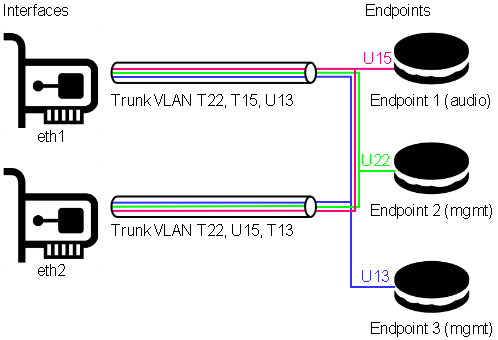 In this example, both physical ports are carrying VLANs 13, 15, and 22.
-
VLAN 13 is the untagged (native) VLAN on eth1 and gets tagged while flowing towards eth2, and vice versa. It’s also received by Endpoint 3, which is a management endpoint. The IP address (fixed or statically assigned) of Endpoint 3 can be reached on eth1 using no VLAN tag and on eth2 using a VLAN tag 13.
-
VLAN 15 is the tagged VLAN on eth1 and gets untagged while flowing towards eth2 (native), and vice versa. It’s also received by Endpoint 1, which is the audio endpoint. The IP address (fixed or statically assigned) of Endpoint 1 can be reached on eth1 using VLAN tag 15 and on eth2 using no VLAN tag.
-
VLAN 22 is a tagged VLAN which flows over both physical interfaces. It’s also received by Endpoint 2, which is a management endpoint. The IP address (fixed or statically assigned) of Endpoint 2 can be reached on any of the two physical interfaces using a VLAN tag 22.
On the Front Display
The front panel display shows the current network configuration, including how to access the shown IP address. If multiple endpoints exist, the line scrolls every 5 seconds to display all endpoints.
Syntax: physical[:Tagged VLAN]>Endpoint name > IP Address (CIDR notation).
Examples
Following the example above:
- eth1 > Endpoint 3 > 192.168.1.20/24 (See the description above on how to access 192.168.1.20)
- eth1:15 > Endpoint 1 > 192.168.5.20/24 (See the description above on how to access 192.168.5.20)
Configure
Select in the top menu System > Network > Settings
Continuing with the example above, this would look like:
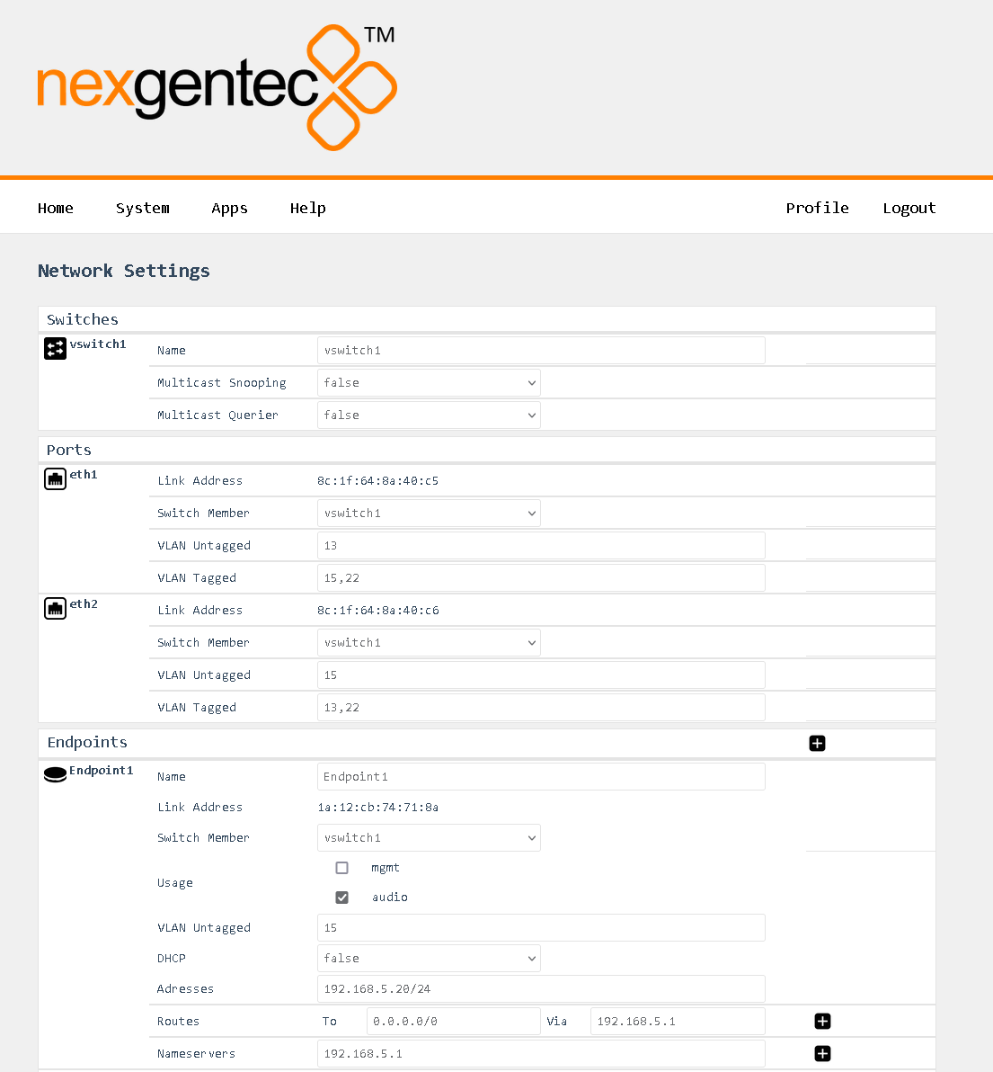
Detailed Field Descriptions for “Switches”
Name
- Read-only: This field displays the name of the switch to be configured. “vswitch1” is the switch to be configured. Currently, only one virtual switch is allowed.
Multicast Snooping
- This setting allows the switch to observe and learn the multicast groups and associated members to limit the forwarding of multicast traffic. Use with caution. If you experience any problems with multicast streams flowing towards the unit or passing through it, turn this setting off.
Multicast Querier
- This setting allows the switch to send out network queries to determine which hosts belong to which multicast groups. It will be automatically set to false once the Endpoint for Audio is included in a tagged VLAN on any of the physical ports. Use it only when there is no managed switch in the network that could send out the query.
Detailed Field Descriptions for “Ports”
Link Address
- Read-only: This field displays the MAC address assigned to the port.
Switch Member
- This setting determines whether to include or exclude the physical port from being used by the managed switch.
VLAN Untagged
- This setting allows you to specify which VLANs should have their tags removed when traffic is sent out of this port.
VLAN Tagged
- This setting allows you to specify which VLANs should retain their tags when traffic is sent out of this port.
Detailed Field Descriptions for “Endpoints”
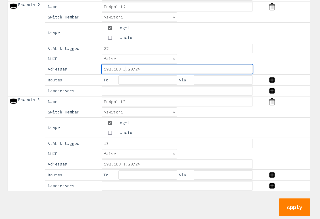
Name
- Read-only: This field displays the name of the endpoint.
Link Address
- This field displays the MAC address assigned to the endpoint.
Switch Member
- This setting determines in which virtual switch the endpoint should be included.
Usage
- This field indicates how the endpoint is being used in the network setup, either for Control, Audio, or both.
VLAN Untagged
- This setting allows you to specify which VLANs should be included and have their tags removed when traffic is sent out of this endpoint.
DHCP
- This setting enables or disables the Dynamic Host Configuration Protocol (DHCP) for the endpoint. If enabled, the endpoint will automatically receive an IP address from the DHCP server in the network.
Addresses
- This field displays the IP addresses assigned to the endpoint. The notation is in CIDR notation.
Routes (To)
- This field displays the routing table for the endpoint, showing where traffic will be directed. To add a default route (gateway), enter To: 0.0.0.0/0 Via: Gateway Address.
Nameservers
- This field displays the IP addresses of the DNS servers that the endpoint is configured to use.